Reports from the Heart of the Machine
Machine Heart Editorial Department
How long does it take to build a lidar from scratch?
LiDAR is an abbreviation for laser detection and ranging system, which is widely used in unmanned driving and sweeping robots. This wide range of applications benefits from the improved performance of lidar on the one hand, and the reduction in its cost on the other hand.
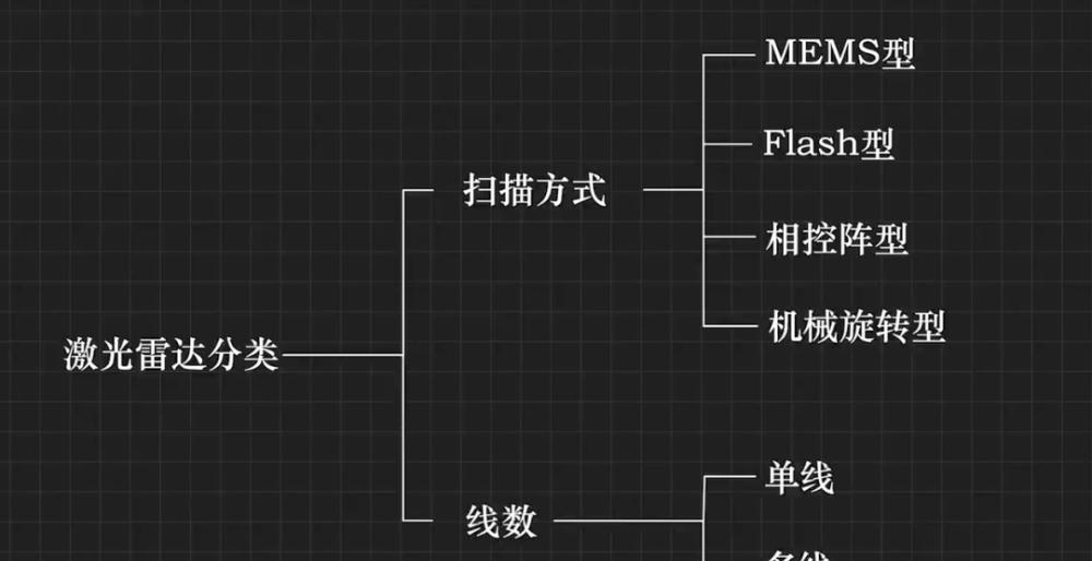
According to the scanning method, lidar can be divided into MEMS type, Flash type, phased array, mechanical rotation type; according to the number of lines, it can be divided into single-line type and multi-line type:
Then again, is it possible to make a lidar? A hard-core UP master of Station B, "Don't want to live in the technical house", really achieved this small goal.
UP master spent more than half a year of spare time, using a laser ranging sensor to complete a single-line mechanical rotary lidar, including a total of hardware design, structural design, FPGA development and 3D printing steps. For the UP Lord, this is not a new challenge, but only a "review of what you have learned before":

Although the UP owner is very modest, many people can only say "I don't understand, but I am shocked" after playing the video:
What are the basic components needed to make a lidar?
UP mainly selected an FPGA development board, the main chip is Xilinx ZYNQ7000, the board is equipped with an HDMI interface that can output up to 1080p60 frames of video, 32 GPIOs (Universal Input and Output Interface) and other peripherals. On this development board, the acquisition, calculation and display of radar data will be completed.
In addition, there is a DC reducer, rated voltage of 12V, deceleration ratio of 1:30, maximum output speed of 300 rpm, the tail of the motor is installed with 500 lines of photoelectric encoder, through the photoelectric encoder can be obtained the output shaft rotation angle.
Finally, there is a laser ranging sensor with a ranging accuracy of 1cm, a measuring range of 12m, which can be measured 1000 times per second, and the output interface is a serial port.
These are the basic components needed for self-made lidar, and then there is the problem of structural design.
Structural design
Up master said that when the lidar is working, the probe needs to rotate continuously, so the signal transmission of the probe and the base cannot be connected with a wire, otherwise it will cause a winding problem, and he solved the problem through the conductive slip ring. Inside the conductive slip ring is a set of brushes that solve the problem of winding the signal line in the case of rotation:
In this way, the lidar is designed:
The entire lidar is divided into a base and a probe, the probe and the base are connected by a rotating axis, and the laser ranging sensor is fixed to the probe base by screws.
The probe base is also fixed with a rotor PCB inside, and the base part is fixed with a conductive slip ring, motor and stator PCB.
In the actual assembly, the motor output shaft and the conductive slip ring and the center of rotation will not be on the same axis because of the error relationship, and an elastic coupling is used here to compensate for the axial deviation:
A pair of infrared pairs are designed between the probe and the base to determine the initial position of the probe rotation:
At this point, the structural design is complete. The designed structural parts are then supported in 3D printing software, sliced, and finally printed by a 3D printer. The printed probe base, probe cover, and base look like this:
Hardware circuit design
The overall frame is shown in the figure, containing the stator PCB and the rotor PCB:
The following figure is a block diagram of the entire power supply and isolation design, the entire motor control part and other circuits are not actually connected, and the motor does not interfere with other circuits when working:
Then there's the PCB design:
After some assembly (10,000 steps are omitted here), the lidar is ready:
Communication between lidar and FGPA is via a cable. In terms of software design, it is divided into two parts: embedded development on the PS side and FPGA development on the PL side, compared to the development of the PL side. The overall block diagram is as follows:
The main difficulty lies precisely in the FPGA part. Up said: "To superimpose radar data on the video data stream, it cost me a lot of brain cells."
Finally, let's take a look at the actual running effect
Limited by the measurement frequency of the laser distance sensor, the probe rotates once to collect data from 500 points, so the scanning frequency of lidar can only be 2Hz per second.
For the visual effect, the UP master added a radar scan line, and the final effect was still good:
At present, the UP master has uploaded the structure and pcb design files of the lidar in the video to the Github platform, and if you want to be a little friend who wants to play, you can download it.
Project Portal: https://github.com/Messi-xiong/LiDAR.git