Several friends and I are closely following the overall structural design of the 4680, and many online friends have confirmed several problems with me:
(1) How is the top water cooling board above arranged?
(2) How exactly does Busbar deal with it?
(3) How is the battery cell exhaust channel designed, spraying up or down?
By collecting some of the content of Monroe's grandfather and online visit, I want to make a video first, and then write my opinion.
Carefully comparing the Texas 4680 battery system and the 4680 system released in Berlin, there are two different forms of arrangement, that is, two modes of horizontal and vertical, corresponding to two different water-cooled plates, and two different modes of arrangement in the X and Y directions of the vehicle.
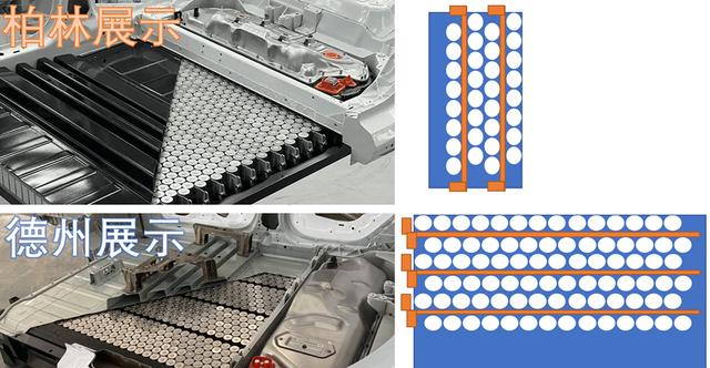
Figure 1. Berlin and Texas showcase two different design ideas
Display area for Part 1 batteries
In the display area of the battery, Tesla hoisted each part separately and divided it into:
4680 battery cell
4680 battery array
Bandolier: I don't know what that is
Potting: I don't know what that is
High Voltage Terminals: This is similar to the entire high voltage interface section
BMS: This one lights up in the video
Exhaust channels
Top cover

Figure 2. Tesla's battery system display stand
For ease of understanding, I've reorganized this structure as follows:
In the previous Tesla's own video, there is a structure of a set of battery arrays, and we see that the batteries below are supported by plastic insulation. In the prevention and control video. We can see that this base design has a certain gap. From a manufacturing point of view, this realizes the assembly rationality of cell production to battery array, and then directly stacks the battery array into the battery Pack through mechanical handling.
The exposé photo in the picture below is actually in line with the horizontal design of Berlin, and the Busbar connection between the two designs is not particularly different in my understanding.
Figure 3. The design structure of the battery module
And from the design idea, the pressure relief of the CTC stage battery cell has to go down, and the water cooling plate is covered on it, which has the advantage of being able to isolate the top. From the actual design concept, this water-cooled board is more for the 360kW supercharge and the current cell internal resistance increased. May not have this thing at the beginning, single-sided cooling can be compatible with the current fast charging power, with the decline of the internal resistance of the battery cell, the water cooling plate on the above scheme is also easier to take away.
Figure 4. The design of the water cooler plate is additional
Figure 5. The situation shown on site
In fact, this bag is designed with 4 pressure relief valves, so there should be a larger pressure relief channel than the previous 21700, and the upper area is a very panic for consumers once the heat goes up due to direct interaction with the body personnel.
Figure 6. Pressure relief design
Structural features of the Part 2 4680 battery
In the battery system, I think Deloitte's judgment is still very interesting. But the way the square shell, blade and cylinder use the shell is different, the former two can achieve 200-300Ah, the latter only 25Ah, the corresponding 100kWh number of cells is about 100-120 corresponding to 900-1000. Therefore, in the structural design, the clever use of pressure relief design, similar to the pressure relief channel to combine the battery cells into an array, and then through the low-density glue to achieve integration, can play a great tactical value in the assembly process.
Figure 7. Different types of development
Summary: I understand that the elasticity of the large cylindrical battery in the design is very large, for the water-cooled design can be added or subtracted, the structural cost of the entire package is not high, there is still room for improvement.