1. Power factor and efficiency test
First, the purpose:
Testing S.M.P.S. power factor, efficiency EFFICIENCY (specifications designed according to customer requirements).
Ii. Use of instruments and equipment:
(1). AC SOURCE / AC power supply;
(2). ELECTRONIC LOAD / Electronic Load;
(3). DIGITAL VOLTAGE METER (DVM) / DIGITAL VOLTMETER;
(4). AC POWER METER / Power Meter;
III. Test conditions:
Fourth, the test method:
(1). Set the test conditions according to the specifications: input voltage, frequency and output load.
(2). Read the Pin and PF values from the POWER METER, and read the output voltage, calculate Pout.
(3). Power factor = PIN / (Vin*Iin), efficiency = Pout / Pin * 100%;
V. Test circuit diagram:
2. Energy efficiency testing
Test whether the S.M.P.S. energy efficiency value meets the requirements of the corresponding national energy efficiency level standards (the specifications are defined according to the requirements of the national standards).
(3). AC POWER METER / power meter;
(1). Input voltage conditions are 115Vac/60Hz and 230Vac/50Hz and 220Vac/50Hz/60Hz conditions.
(2). Output load condition is no load, 1/4 max. load、2/4 max. load、3/4 max. load、max. Load five load conditions.
(1). The product is preheated for 30 minutes under its nominal output load conditions before testing.
(2). Record the input power (Pin), input current (Iin), output voltage (Vo), power factor (PF) at input of 115Vac/60Hz and 230Vac/50Hz in order from large to small, and then calculate the efficiency of each conditional load.
(3). When no load, only the input power (Pin) and input current (Iin) need to be recorded.
(4). Calculate the average efficiency of the four loads at 115Vac/60Hz and 230Vac/50Hz, which is the efficiency value of energy efficiency
V. Standard Definition:
CEC / US EPA / Energy Efficiency Specification Value Standards (Class IV) in Australia and New Zealand;
(1). The specifications for class IV efficiency are: 1). Po
2).1≤Po≤51W,Average Eff.≥0.09*Ln(Po)+0.5; 3). Po>51,Average Eff.≥0.85.
(2). The specification of the input no-load power is: 1).0
(3). Po is the product of the rated output voltage and the rated output current indicated on the nameplate;
(4) The average efficiency value of the actual test and the input no-load power value must meet the specification requirements at the same time to meet the standard requirements.
Sixth, the calculation method examples:
(1). The energy efficiency efficiency of 12V/1A = (0.09*ln12+0.5)*100%= (0.09*2.4849+0.5)*100%=72.36%;
(2). Input power ≤ 0.5W;
3. Input current test
Test S.M.P.S. input current RMS INPUT CURRENT (specifications are designed according to customer requirements).
(1). Set the test conditions according to the specifications: input voltage, frequency and output load;
(2). Record the AC INPUT current value from the power meter;
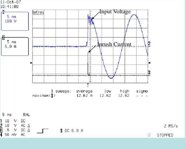
4. Inrush current test
Test S.M.P.S. input inrush current, whether it meets SPEC requirements.
(3). OSCILLOSCOPE / oscilloscope;
(1). According to SPEC. Required (usually defined as an input voltage of 100-240Vac/50-60Hz).
(1). According to SPEC. It is required to set the input voltage and frequency, and set the output load of the product to be measured at MAX. LOAD.
(2). SCOPE CH2 is connected to CURRENT PROBE to measure INRUSH CURRENT, CH1 is set in DC Mode, VOLTS/DIV setting is subject to availability, CH1
As SLICE's VIGOR SOURCE, TRIGGER SLOPE is set to "+", TIME/DIV is better than 5mS, and TRIGGER MODE is set to "NORMAL".
(3). CH1 is connected to the AC input voltage.
(4). After the above settings are completed, power ON, find out the STRIKER operating current value (AT 90o or 270o POWER ON).
V. Precautions:
(1). Cold-START: it needs to be in a low (normal) temperature environment and the TORCH Cap charge must be exhausted, and the thermistor is also at room temperature, and then it can only be started for the first time.
If you need to start the second time, you must wait for the charge to be exhausted before you can start the test again.
(2). OSCILLOSCOPE requires the use of isolation transformers.
Sixth, the test circuit diagram:
5. Voltage regulation test
When the S.M.P.S. OUTPUT LOAD is measured and ac line changes, its output voltage follows the stability of the change (conventional definition≤1%).
(1). Set the test load LOAD condition according to the specifications.
(2). Adjust the input voltage AC LINE and frequency FREQUENCY value.
(3). Record whether the output voltage value of the product to be measured is within the specification.
(4). Line reg.=(Maximum output voltage (Vmax.) - Minimum value of output voltage (Vmin.)) /Vrate volt.*100%.
V. Notes:
(1). Before the test, the heat machine to be tested will be tested first, and then tested after its output voltage is stabilized.
(2). The voltage regulation rate value is the value calculated when the output load is unchanged and the input voltage changes.
6. Load regulation rate test
Test S.M.P.S. When the AC LINE is certain and the OUTPUT LOAD changes, its output voltage follows the stability of the change (conventional definition≤±5%).
(1). Set the test input voltage AC LINE and frequency FREQUENCY value according to the specifications.
(2). Adjust the output load LOAD value
(4). Load reg.=(Maximum/small value of output voltage (Vmax/min.) - Output voltage rating (Vrate))/Vrate volt.*100%.
(1). Before the test, the heat machine of the product to be tested is first tested, and then tested after its output voltage is stabilized;
(2). The load regulation rate value is the value calculated when the input voltage is unchanged and the output load changes.
7. Enter the slow-moving test
Verify that when the input voltage is low, the product to be measured needs to be able to protect itself and cannot be damaged.
(1). According to SPEC. Requirements: Set the input voltage to 90Vac or 180Vac and the output load Max. load;
(1). Connect the product to be measured with the input power supply and electronic load, and set the input voltage and output load;
(2). Step down the input voltage at 3 Vac/min each time.
(3). Record the voltage value (including input voltage and output voltage) until the product to be measured automatically stops.
(4). Set the input voltage to 0Vac, gradually increase the input voltage, 3 Vac/minute each time,
Until the output voltage of the product to be measured reaches the normal specification, the output voltage and input voltage values at the time of voltage start-up are recorded.
(1). The product to be tested should not have any unstable action under normal operation, as well as failure;
(2). The input voltage of the product when the product is started and started should be less than the lower limit of the input voltage range.
8. Ripple and noise test
Test S.M.P.S. ripple ripple and noise NOISE of DC output voltage (specification definition is conventionally 1% of ≤ output voltage);
(3) OSCILLOSCOPE / oscilloscope;
(4) TEMP. CHAMBER / Temperature Control Room;
Various LINE and LOAD conditions and temperature conditions, various input voltages & output loads (Min.-MAX. LOAD).
(1). According to the test loop, connect each test instrument, equipment, and product to be tested, and test the power supply in various LINE and LOAD, and temperature conditions of RIPPLE & NOISE (the following figure is a typical output RIPPLE & NOISE A: RIPPLE+NOISE; B: RIPPLE; C: NOISE
(1). Before testing, the output to be tested is paralleled to SPEC. Specified filter capacitors, (typically 10uF/47uF electrolytic capacitors; or tantalum capacitors and 0.1uF ceramic capacitors) bandwidth limits depending on SPEC. Depending on (usually 20MHz).
(2). Noise caused by interference with the oscilloscope probe itself should be avoided.

9. Rise time test
When testing S.M.P.S. POWER ON, the output of each group rises from 10% to 90% POINT (generally defined as ≤20mS).
(3). OSCILLOSCOPE / Oscilloscope
(1). Set AC VOLTAGE, FREQUENCY AND LOAD according to the specifications.
(2). SCOPE CH1 is connected to Vo, and set to STRIKER SOURCE, LEVEL is set at 60% ~ 80% of Vo is more appropriate, TRIGGER SLOPE is set at "+",
TIME/DIV and VOLTS/DIV depend on the output voltage.
(3). Use "TIME" in CURSOR to measure the rise time of the output of each group of products to be measured from 10% to 90% of the voltage.
Before testing, the product to be tested is in a cold state, and then wait for buck Cap. Test after the charge is exhausted.
10. Drop time test
When testing S.M.P.S. POWER ON, the output of each group drop time from 90% to 10% POINT (conventional definition≥5mS);
(1). According to the specifications, AC VOLTAGE, FREQUENCY AND LOAD.
(2). SCOPE CH1 is connected to Vo and set to STRIKER SOURCE, LEVEL is set at 60% ~ 80% of Vo, TRIGGER SLOPE is set at "-", TIME/DIV and VOLTS/DIV depend on the output voltage;
(3). Use "TIME" in CURSOR to measure the output of each group of products to be measured from 90% to 10% of the voltage drop time.
Before the test, the heat machine of the product to be tested is first tested, and then tested after its output voltage is stabilized.
11. Boot delay time test
When testing S.M.P.S. POWER ON, the time difference between the input voltage AC LINE and the output (generally defined as ≤3000mS).
(1). During the test, the AC LINE, FREQUENCY and output load are set according to the specifications (generally LOW LINE & MAX. Load time is the longest).
(2). OSCILLOSCOPE's CH1 is connected to the VO as TRIGGER SOURCE, CH2 to AC LINE.
(3). Trigger LEVEL is set between 60% and 80% of Vo, TRIGGER SLOPE is set at "+", volts/DIV and TIME/DIV are subject to availability.
(4). Use "TIME" in CURSOR to measure the time difference between AC ON and Vo LOW LIMIT.
(1). Before testing, the product to be tested is in a cold state, and the BAK Cap. Test after charge exhaustion;
(2). Oscilloscope requires an isolation transformer.
12. Shutdown maintenance time test
The time difference between the input voltage AC LINE and the output OUTPUT when testing S.M.P.S. POWER OFF (general definition≥10mS/115Vac & ≥20mS/230Vac);
(1). During the test, set AC LINE, FREQUENCY and output load according to the specifications.
(2). OSCILLOSCOPE's CH1 is connected to the Vo for VIGOR SOURCE, CH2 to ACLINE.
(3). Trigger LEVEL is set between 60% and 80% of Vo, TRIGGER SLOPE is set at "-", VOLTS/DIV and TIME/DIV are subject to availability.
13. Output overshoot amplitude test
When testing S.M.P.S. POWER ON, the output DC OUTPUT overshoot amplitude change (generally defined as ≤10%).
According to SPEC. Required, input voltage range and output load (Min. – Max. load).
(2). OSCILLOSCOPE's CH1 connection vo is VIGOR SOURCE;
(3). Trigger LEVEL is set between 60% and 80% of Vo, TRIGGER SLOPE is set at "+" and "-", volts/DIV and TIME/DIV are subject to availability.
(4). Use "VOLT" in CURSOR to measure the relationship between the output overshoot point and the stable value of the product to be measured.
(5). ON / OFF do ten times each, overshoot amplitude % = △V / Vo * 100%;
Products in BOTH CC and CR modes need to meet the specifications.
14. Output transient response test
When the output load of S.M.P.S. is tested, the output voltage is stable with the change (the specification defines that the maximum and minimum voltage values do not exceed ±10% of the output specification).
According to SPECA. regulations: input voltage AC LINE, changing load LOAD, frequency and ramp slope SR/F value.
(1). Set the input voltage AC LINE and frequency OF THE PRODUCT to be tested during the test.
(2). Set the output conditions of the product to be tested during the test: change load and change frequency and lift slope.
(3). OSCILLOSCOPE CH1 is connected to the OUTPUT detection point to measure the change in its voltage.
(4). CH2 is connected to the CURRENT PROBE test output current, as THE VIGOR SOURCE of OSCILLOSCOPE.
(5). TRIGGER MODE is set to "AUTO.".
(1). Note that when using CURRENT PROBE, every time you change the VOLTS/DIV scale PROBE, you must zero ZERO,
(2). DEGAUSS and ZERO ZERO MUST BE PERFORMED FREQUENTLY DEGAUSS AND ZEROING ON CURRENT PROBE.
15. Overcurrent protection test
Test s.M.P.S. whether the output current is protected when the output current is too high, whether the protection point is within the specifications, and whether it will be protected by S.M.P.S. Causes damage (The overcurrent point is conventionally defined as the output negative rating.)
Loaded 1.2-2.5x / CV mode product initial outside).
According to SPEC. Specified: Input voltage AC LINE and electronic load.
(1). Set the output load of the group to be measured in MAX. LOAD.
(2). Increment at a certain slope (usually 1.0A/S), increase the output current until the power supply is protected, and when protected, the increased current value is decreased, depending on whether the output will automatically reunite.
(3). OSCILLOSCOPE CH2 is connected to current PROBE to detect the output current with PROBE.
(4). CH1 is connected to the output voltage to be measured as the VIGOR SOURCE of OSCILLOSCOPE.
(5). TRIGGER SLOPE is set to "-", TRIGGER MODE is set to "AUTO", TIME/DIV depends.
(3). The product must not be generated by safety hazards.
16. Short circuit protection test
Test whether the S.M.P.S. output is protected before power-on or when the product is short-circuited during operation.
(4). Low impedance short-circuit clip
According to SPEC. Specified: Input voltage AC LINE and load LOAD value and low impedance short-circuit clamp.
(1). Set the test conditions according to the specifications: input voltage AC LINE and load LOAD value (generally MAX.LOAD).
(2). Each group of outputs is short-circuited to each other or short-circuited to the ground, and the output characteristics are detected.
(3). Short-circuit ON THEN short & SHORT AFTER short-circuit short-circuit TURN ON 10 times each.
(1). When SHORT CIRCUIT is excluded, detect whether the product to be tested is automatically restored or needs to be restarted (subject to SPEC requirements), and test whether the product is normal or whether there is damage to parts (product requirements should be normal).
(2). The product must not be generated with safety hazards.
17. Overvoltage protection test
Test whether S.M.P.S. is protected when the output voltage is too high, whether the protection point is within the specifications, and whether it will be protected against S.M.P.S. Causes damage (general definition: Vout
(4). DC SOURCE / DC power supply;
According to SPEC. Specified: Input voltage AC LINE and load LOAD value.
(1). Test method 1: Remove the feedback feedback of the product to be tested, and find out the overvoltage protection OVP point.
(2). Test method 2: add a variable voltage to the output of the product to be measured, slowly increase the voltage value, and find out the overvoltage protection OVP point.
(3). OSCILLOSCOPE CH1 is connected to the OVP detection point to measure the change in its voltage.
(4). CH2 is connected to another set of output voltages as THE VANGUARD SOURCE of OSCILLOSCOPE.
(5). TRIGGER SLOPE is set to "-", TRIGGER MODE is set to "NORMAL".
The product must not be generated with safety hazards.
18. Heavy and light load variation test
Test the effect of the output load of S.M.P.S. on the output voltage during light and heavy load switching (the specification defines the maximum and minimum voltage values not exceeding ±10% of the output specification).
According to SPEC. Specified: Input voltage AC LINE and load LOAD(MIN. AND MAX.) value.
(1). Set AC VOLTAGE, FREQUENCY AND LOAD (MAX. LOAD and MIN. LOAD).
(2). SCOPE CH1 is connected to Vo and set to STRIKER SOURCE, LEVEL is set at 90% ~ 100% of Vo is more appropriate, TRIGGER SLOPE is set at "+", VOLTS/DIV depends on the output voltage.
(3). TIME/DIV is set to 1S/DIV or 2S/DIV for scrolling.
(4). When the input voltage is stable, the output load (max/min) is changed.
(5). Test the maximum and minimum values of the output voltage at the set voltage.
not
19. Input voltage fluctuation test
Test whether the input voltage of S.M.P.S. will be .M to S.P.S. when the input voltage of the S.P.S. changes within the specification requirements. Causes damage or unstable output.
(1). Set the output load to be measured in MAX. LOAD and MIN. LOAD.
(2). TRIGGER SLOPE is set to "+", TRIGGER MODE is set to "AUTO", TIME/DIV is 1S/DIV or 2S/DIV depending on the situation.
(3). Variable input voltage, such as: 90Vac-180Vac; 115Vac-230Vac; 132Vac-264Vac;0-90Vac...... 0-264Vac.
(4). Test the maximum and minimum values of the output voltage when the input voltage fluctuates.
The range of output voltage variation should be within the specification voltage requirements.
20. Power switch cycle test
Test whether S.M.P.S. can withstand the shock of continuous switching operation.
(4) POWER ON/OFF TESTER / Power Switch Tester;
(1). Input voltage: 115Vac/230Vac Output load: full load.
(2). ON/OFF时间: ON 5秒/ OFF 5秒ON/OFF CYCLE:AT LEAST 5000 CYCLE.
(3). Ambient temperature: room temperature.
(1). Connect the product to be tested to the power supply on/off tester and power supply. (115Vac and 230Vac & full load, or according to customer specifications)
(2). S.M.P.S OFF 5 seconds and ON 5 seconds for one cycle, the total test period: 5000 CYCLES.
(3). During the test process, when each 1000 cycles are completed, the input power and output voltage of the product are recorded.
(4). After the end of the test, determine whether there is a difference in the electrical performance of the product to be tested before and after the test.
During the test or during the test completion phase, the product to be tested must be able to operate normally and there should be no performance degradation.
21. Element temperature rise test
Test S.M.P.S. Temperature rise condition of the component in the specified operating environment, voltage, frequency and load conditions.
(3). HYBRID RECORDER / HYBRID RECORDER (DR130);
(4). TEMP. CHAMBER / Temperature Control Room;
According to SPEC. Specifications: Input voltage AC LINE, frequency FREQUENCY, output load LOAD and ambient temperature.
(1). According to the line situation, the components with higher temperature rise are first determined, and then the determined components are pasted with the temperature rise line.
(2). Set the test conditions according to the specifications (AC LINE AND OUTPUT LOAD) and then start the machine, and record the input power and output voltage.
(3). Record the temperature rise curve of the component with the hybrid recorder HYBRID RECORDER, print the result after the temperature rise of the component is completely stable, and record the input power and output voltage.
(1). The coupling point of the temperature rise line should be attached to the component test point as much as possible, and the temperature rise line trend should be avoided as much as possible to affect the heat dissipation of the S.M.P.S component.
(2). The sample to be tested should simulate its actual or placement status in the system.
(3). For fanless (NO FAN) products, the test should try to avoid the influence of external wind flow on it.
22. High temperature operation test
Test the influence of high temperature environment on the structure, components and electrical of S.M.P.S. during operation, to consider S.M.P.S. Rationality of structural design and part selection.
(5). HI-POT TESTER / High Voltage Tester
(1). According to SPEC. requirements: input condition (RATED VOLTAGE), output load (FULL LOAD) and operating temperature OPERATION TEMP (usually temperature: 40 °C);
(2). Test time: 4Hrs.
(1). Place the product to be tested in the temperature control room, set the input and output test conditions according to the specifications, and then start the machine;
(2). Set the temperature and humidity of the temperature control room according to the specifications, and then start the temperature control room;
(3). Record the input power and output voltage of the product to be measured regularly, and whether there is any abnormality in the product to be measured;
(4). After the test, return to room temperature, and then remove the product to be measured from the temperature control room, and recover at room temperature for at least 4 hours.
(1). During and after the product test, the product performance cannot be degraded and degraded.
(2). The dielectric strength and insulation resistance test of the product after the test shall meet the requirements of the specification.
23. High temperature and high humidity storage test
To test the influence of high temperature and high humidity storage environment on the structure, components and electrical of S.M.P.S. to consider S.M.P.S. Rationality of structural design and part selection.
Storage temperature and high humidity conditions: usually temperature 70±2 °C, humidity 90-95% test time 24Hrs (non-operating conditions).
(1). Record the input power, output voltage and HI-POT status of the product to be measured before the test;
(2). The confirmed product to be measured is placed in the constant temperature and humidity machine, the temperature and humidity are set according to the specifications, and then the temperature control room is started;
(3). Test 24Hrs, place at least 4Hrs in the air after the test, and then confirm whether there are abnormalities in the appearance, structure and electrical properties of the product to be tested.
24. Low temperature operation test
Test the influence of low temperature environment on the structure, components and electrical of S.M.P.S. during operation, in order to consider S.M.P.S. Rationality of structural design and part selection.
(5). HI-POT TESTER / High Voltage Tester;
(1). According to SPEC.requirements: input conditions (RATED VOLTAGE), output load (FULL LOAD) and operating temperature (OPERATION TEMP.), usually temperature: (0 °C).
(1). Place the product to be tested in the temperature control room, set the input and output test conditions according to the specifications, and then start the machine.
(2). Set the temperature of the temperature control room according to the specifications, and then start the temperature control room.
(4). After the test, the product to be tested is removed from the temperature control room, recovered at room temperature for at least 4 hours, and then confirm whether its appearance and electrical performance are abnormal.
25. Low temperature storage test
To test the influence of low temperature storage environment on the structure, components and electrical of S.M.P.S. to consider S.M.P.S. Rationality of structural design and part selection.
Storage temperature conditions: usually temperature -30 °C, test time 24Hrs (non-operating conditions).
(1). Record the input power, output voltage and HI-POT status of the product to be measured before the test.
(2). Place the confirmed tested product into the constant temperature and humidity machine, set its temperature according to the specifications, and then start the temperature control room.
(3). Test 24Hrs, place at least 4Hrs in the air after the test, then do HI-POT testing of the tested product, record the test results, and then confirm whether the appearance, structure and electrical performance of the tested product are abnormal.
26. Low temperature start test
Test the effect of low temperature storage environment on the electrical effect of S.M.P.S. to consider S.M.P.S. Rationality of electrical and part selection.
Storage temperature conditions: Usually reduced to -10 ±2 °C at operating temperature 0 °C, storage time is at least 4Hrs.
(3). The test temperature is stored at least 4Hrs, and then switched on and off 20 times each at 115Vac/60Hz & 230Vac/50Hz and the output maximum load respectively, to confirm whether the electrical performance of the product to be tested is normal.
(1). During or after the product performance test, the product performance cannot be degraded and degraded.
(2). The set ambient temperature is the temperature of the operating low temperature and then drops by -10 degrees.
27. Temperature cycling test
The test is an acceleration test for all components of the S.M.P.S. to reveal problems that may occur in practice.
Operating temperature conditions: Typically low temperatures -40 °C, 25 °C, 33 °C and high temperatures of 66 °C (humidity: 50-90%), tested for at least 24 cycles.
(2). Put the confirmed product to be tested into the constant temperature and humidity machine, in an unpackaged, non-operating state.
(3). Set the temperature sequence to 66±2 °C for 1 hour, 33±2 °C and humidity 90±2% for 1 hour, -40±2 °C for 1 hour, 25±2 °C and humidity 50±2% for 30 minutes for a cycle.
(4). Start the thermostat, then record its temperature and time graph, monitor the process recorded by the system,
(5). After the test is completed, the temperature returns to room temperature and then the analyte is removed from the constant temperature and humidity machine, and the sample is placed in the air for 4Hr to confirm the appearance, structure and electrical performance are abnormal.
(1). After the cold and thermal shock test, the performance and appearance of the product cannot be degraded and degraded.
(2). After the cold and thermal shock test, the dielectric strength and insulation resistance of the product should meet the requirements of the specification.
28. Hot and cold shock test
Test high and low temperature shocks against S.M.P.S. The effect is used to expose the weaknesses of each constituent element.
(1). According to SPEC. Requirements: Storage up to (70 °C), low temperature (-30 °C), test a total of 10 cycles, high and low temperature conversion time
(2). According to the test conditions provided by the customer.
(1). In the temperature control room, the product to be measured is changed from normal temperature of 25 °C to low temperature, usually -30 °C, and baked at low temperature of 1Hr.
(2). The temperature control room changes from low temperature -30 °C to high temperature is usually 70 °C, the transition time is 2min., and the high temperature baking is 1Hr.
(3). After 10 cycles between high temperature 70 °C and low temperature -30 °C, the temperature returned to room temperature will be S.M.P.S. Remove (recover at least 4 h).
(4). Confirm whether the label, housing, voltage resistance and electrical properties of the product to be tested are different from those before the test.
(3). The product is non-operating condition.
29. Hot and cold shock test
Test S.M.P.S. under the specification of the withstand voltage and time conditions, whether the arc ARCING, its CUT OFF CURRENT meets spec. requirements, and whether there will be damage to S.M.P.S.
(4). HI-POT TESTER / High Voltage Tester;
According to SPEC. Requirements: Withstand voltage value (4242Vdc / 3000Vac), operating time (1 minute) and CUT OFF CURRENT (3.5mA) value;
(1). According to SPEC. Set the withstand voltage WITHSTANDING VOLTAGE, operating time time, CUT OFF CURRENT value.
(2). Connect the product to be tested with the withstand voltage tester according to the requirements, conduct the withstand voltage test, and observe whether there is arc ARCING, and whether the leakage current CUT OFF CURRENT is too large.
(3). After the withstand voltage test, confirm whether the input power and output voltage of the product to be tested are normal.
(1). Before testing, the test conditions of the withstand voltage tester should be set, and the input and output of the product to be tested should be in good contact with the tester.
(2). The specification value of the pressure resistance is set with reference to the safety requirements.
30. Drop test
Understand the drop of S.M.P.S. by a certain height, different sides, its structure, electrical and other characteristics of the change.
According to SPEC. Requirements: Specified drop height, number of drops and stiff level.
(1). All products to be tested need to undergo electrical testing and visual inspection to ensure that there is no visible damage before the test.
(2). Determine the order of the six faces (small-large) to fall in turn.
(3). The test points to be tested are dropped once by the specified height and item (2), and each drop must be confirmed by its electrical and insulation, and normal or abnormal results must be recorded.
31. Insulation impedance test
Measure the insulation impedance value between the live part of the ante and the output circuit and between the live part and the rubber shell.
(1). According to SPEC. Requirements: The insulation impedance value of the test after applying a 500V DC voltage should be 10MOhm higher (conventional definition).
(1). After confirming the electrical performance, set the applied voltage (500Vdc) and the test time (1 Minute) in the insulation impedance tester.
(2). Short-circuit the input and output of the analyte to be connected separately, and then connect the tester to the corresponding end for testing.
(3). Then connect the input terminal of the object to be tested and the corresponding end of the tester with the corresponding end of the tester.
(4). Confirm whether the test insulation impedance value of the tested object is higher than the SPEC.
(1). The impedance requirement value is defined according to the requirements of the safety standard.
32. Rated voltage output current test
Test S.M.P.S. on AC LINE and OUTPUT VOLT. At a certain time, its output current value.
(1). Fixed input voltage and frequency, set the output voltage in CV mode according to the conditions.
(2). After power-on, the output current value is recorded when the output is stable.
(3). Switch the input voltage and frequency, and record the output current value when the input voltage is different.
(4). The output current value is recorded separately under different conditions of output voltage value.
The current value of the product to be measured needs to be stable before recording the output current value.