--Collect the "Automotive Driving Automation Classification" (GB/T 40429-2021)--
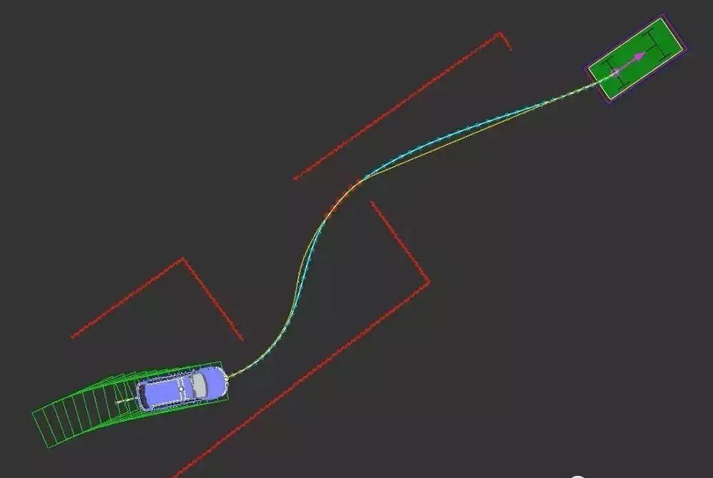
Driverless car path planning refers to the fact that on the basis of a certain environmental model, after giving the starting point and target point of the driverless car, an effective path without collision and safely reaching the target point is planned according to the performance indicators.
Route planning consists of two main steps: establishing an environment map containing obstacle areas and free areas, and selecting an appropriate route search algorithm in the environment map to quickly and real-time search for drivable routes. The results of the route planning play a guiding role in the vehicle's travel. It guides the vehicle from its current position to the target location.

Environment map representation method
According to different representations, the environment map representation method is mainly divided into metric map representation, topological map representation, etc.
Metric map notation
The metric map representation uses whether the grid in the coordinate system is occupied by obstacles to describe the characteristics of the environment, which is divided into geometric representation and spatial decomposition.
Geometric notation uses geometric elements including points, lines, and polygons to represent environmental information. Compared with other environment map representations, geometric feature maps are more compact, which is conducive to location estimation and target recognition; the disadvantage is that it is difficult to extract environmental geometric features. Geometric feature maps are suitable for extracting some simple geometric features in an indoor environment where the environment is known, while geometric features in outdoor environments are more difficult to extract. Commonly used geometric maps include Voronoi diagrams, probability road diagrams, etc.
Geometric notation
Parking volonoi figure
Spatial decomposition is the decomposition of the environment into local units similar to a grid, and the state is described according to whether they are occupied by obstacles. A barrier grid if the grid unit is occupied by an obstacle, or a free grid if it is not. The spatial decomposition method usually uses a uniform decomposition method and a step-by-step decomposition method based on the grid size. The grid size in the uniform decomposition method is evenly distributed, and the occupied grid is represented numerically. The uniform decomposition method can quickly and intuitively integrate sensor information; however, the uniform decomposition method uses the same size grid to lead to a large storage space and a high degree of complexity in path planning calculations in large-scale environments. In order to overcome the problem of huge storage space in the uniform decomposition method, the step-by-step decomposition method decomposes the environmental space into rectangular areas of different sizes, thereby reducing the memory space occupied by the model.
Uniform decomposition method
Quadrangle decomposition method
Uniform grid maps are the most commonly used in metric map path planning. It breaks down the environment into a series of discrete grid nodes. All grid nodes are uniform in size and evenly distributed. The grid uses the value occupation method to represent obstacle information. For example, using the simplest binary representation, 1 represents barrier fence, which is impassable, and 0 represents free grid.
When the environment information is represented with a uniform grid map, only a certain connection relationship between the grid nodes can ensure that the effective path from the starting point to the target point can be searched.
Eight connection methods
Topological map notation
The topology map model uses nodes to represent specific locations on the road and uses the relationship between nodes and nodes to represent the connections between roads. This map representation method has the characteristics of simple structure, convenient storage, good global coherence, high planning efficiency, and strong robustness, which is suitable for road planning in large-scale environments, but it contains less information and requires the help of other sensors to further describe the road environment.
Path planning algorithm
At present, the classification of path planning methods is roughly as follows:
Path map
The more commonly used path planning algorithms are sample-based path planning algorithms and search-based path planning algorithms.
Sampling-based path planning algorithm
Sample-based path planning algorithms have been used in vehicle path planning for a long time, and the more common sample-based planning algorithms are probabilistic road map (PRM) and rapidly-exploring Random Tree (RRT).
The probability graph algorithm randomly selects N nodes in the planning space, then connects the nodes and removes the connection line in contact with the obstacle, thus obtaining a feasible path. Obviously, when there are too few sample points, or the distribution is unreasonable, the PRM algorithm is incomplete, but the sample point can be increased to make the algorithm complete, so the PRM is probabilistically complete but not optimal.
PRM algorithm
Rapid random expansion trees were originally used primarily to solve path planning problems with kinematic constraints. Since RRT uses random sampling in the state space to determine the expansion node, no pre-processing is required and the search speed is fast. Therefore, this algorithm is widely used in path planning problems as a fast search algorithm.
RRT algorithm
Search-based path planning algorithm
The search-based path planning algorithm obtains the final route by searching for an environment map that represents environmental information. The more representative algorithms are the Dijkstra algorithm and the A algorithm.
The Dijkstra algorithm is a typical breadth-first search algorithm. It is a method of producing the shortest path in increasing order of path length and is one of the classic algorithms for solving the shortest path. The Dijkstra algorithm is a greedy algorithm that selects a local optimal solution at each step to produce an optimal solution. This also leads to the high time complexity of the algorithm, and when the graph scale is large, the calculation speed of the algorithm is slow, and it is difficult to meet the requirements of the real-time nature of path planning.
The A* algorithm is a classic heuristic search algorithm that is improved by the Dijkstra algorithm. Its most notable feature is the addition of heuristics in the search process, which reduces the number of search nodes by giving them heuristics, thereby improving the efficiency of path search. Studies have shown that the path obtained by the A* algorithm search can meet both real-time and optimal requirements.
The real environment is far more complex than this, and good planning must build a deep understanding of the surrounding environment, in addition to the establishment of a large number of mathematical equations, as well as the need to consider the influence of obstacles, lane lines, path curvature, curvature change rate, vehicle speed, acceleration and other factors.
Reproduced from the network, the views in the text are only for sharing and exchange, do not represent the position of this public account, such as copyright and other issues, please inform, we will deal with it in a timely manner.
-- END --