Source: HAOMAI Chemical Technology Author: Wei Xiao
With the continuous development of modern industry, some rotating machinery such as turbines (turbines), rotors of engines or motors, computer disk drives, etc. have higher and higher speeds, but with the increase of speed, many new problems have emerged, resulting in a new discipline - rotor dynamics. The main contents of rotordynamic research include critical speed, unbalance response, stability analysis, dynamic balance and bearing bearing support design, etc., while the calculation of ANSYS rotor dynamics mainly includes: critical speed analysis, unbalance analysis, basic excitation response, rotor rotation and system stability prediction, gyroscopic torque generated by rotating parts, considering the influence of bearing flexibility (oil film bearing), unbalance force of rotor model and other excitation force calculations.
Mechanical models and equations of rotordynamics
A typical rotordynamic model is a rotor-bearing system, as shown in Fig. 1. Among them, the bearing support stiffness coefficient is:
Wherein, the bearing stiffness and damping coefficient are both functions of the rotational speed, i.e.:

Fig. 1 Mechanical model of typical rotor dynamics
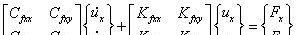
The traditional rotordynamic analysis is carried out by the transfer matrix method, because the large amount of structural information is simplified to a very simple centralized mass - beam model, the integrity of the model and the accuracy of the analysis cannot be ensured; and the finite element can take into account the integrity of the model and the efficiency of the calculation when dealing with the rotor mechanics problem, but the "gyro effect" of the rotor has been the bottleneck problem that restricts the finite element analysis of rotor dynamics for many years. ANSYS solves the problem of the influence of the "gyro effect" in dynamic characterization analysis, and the gyroscopic effect is not limited by the computational model, making rotordynamic finite element analysis simple and efficient. Rotordynamic equations can be described in either a stationary or rotating coordinate system, where the equations are:
In a rotating coordinate system its equations are:
Among them, [M], [C], and [K] are mass, damping, and stiffness, respectively; [Cgyr] is the gyro effect matrix; [Ccor] is the Kochsch effect matrix; and [Kspin] is the rotation softening effect matrix.
Kinetic analysis of a rotor
1. Mechanical model
For a modal analysis of the rotor system, the bearing element is replaced by a spring with a certain stiffness and damping, and the bearing element is defined by inserting a command flow. Set the shaft speed and limit the axial displacement of one plane to avoid rigid body displacement.
Fig. 2 Hinge model
2. Analyze the results
Through the analysis, the natural frequency of the rotor system and the corresponding mode shape can be viewed, so as to analyze the vibration pattern and imbalance mode of the rotor system according to the obtained data analysis, providing the necessary basis for the normal operation of the shaft system, Fig. 3 is the first ten order mode of the shaft.
Mode-I
Mode-II
Mode-III
Mode-IV
Mode-V
Mode VI
Mode-VII
Mode-VIII
Mode-IX
Mode-X
Fig. 3 Ten-order mode shape diagram of the rotor system
In many cases, it is necessary to monitor the dynamic change of several components of the spectrum as the rotor speed changes to determine the operating characteristics of the rotor over the entire speed range, and one of the analytical methods to achieve this purpose is the Campbell diagram. The Campbell diagram is the vibration amplitude of the monitoring point as a function of speed and frequency, and the variation characteristics of all components of rotor vibration in the entire speed range are expressed. In the Campbell diagram, the abscissa represents the rotational speed and the vertical coordinate represents the frequency, showing the change of the natural frequency with the speed of rotation. The forced vibration part, that is, the frequency component related to the speed, is presented on the ray ejected from the origin, while the free vibration part is presented at a fixed frequency line. Fig. 4 is the Campbell diagram of the rotor system, through the Campbell diagram can analyze the critical speed of the rotor, the intersection of each order curve and the straight line of RATIO=1 in the figure is the rotor critical speed, such as the critical speed corresponding to the fourth order mode in the figure is 1566.2 rad/s.
Figure 4 Campbell Diagram
Conclusion
Due to the unevenness of the material, manufacturing, processing and installation errors, etc., the rotor system inevitably has a quality eccentricity, and the rotor may also produce thermal deformation and wear and adsorption of the medium during the working process, which will more or less lead to the increase of the rotor imbalance, so that the unbalanced vibration of the rotor will increase.
The vibration of the rotor system caused by excessive imbalance is very harmful, it reduces the efficiency of the machinery, increases the load, makes some parts easy to wear, fatigue and shorten the life, and the larger vibration will also worsen the operating environment of the operator, and even lead to serious accidents of machine destruction and death. Eliminating or reducing the vibration of the rotor system is first considered to balance the rotor, and the dynamic analysis of the rotor system is indispensable.
bibliography:
[1] Pu Guangyi, ANSYS Workbench Basic Tutorial and Examples[M].Beijing:China Water Resources and Hydropower Press,2014.
Lin Xianliang, Rotor dynamic analysis[D].Chongqing Three Gorges University,2010.
Zhang Hongcai, Kinetic analysis of motor rotor based on ANSYS[J].e-works digital enterprise network.
Li Xiaoling, Sun Defeng, Finite element analysis of rotor dynamic characteristics of units[J].2009(38):54-57.