From the analysis of the previous micro headline, it is known that R2 is not redundant, but plays an important role in eliminating damping oscillations at the edges.
One might ask if capacitor C1, which is connected to the G and S poles, is redundant.
This is not the case, and Gs poles are capacitive, slowing down the moss on-time and helping to reduce Miller oscillations. Prevent the mos tube from burning.
In addition, C1 can play another very important role in the following cases.
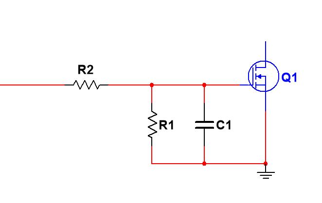
For the circuit in Figure 1, when the control signal output is low, the G pole must be low so that Q1 can be in the cutoff state.
Consider that there will be some abnormal exceptions, such as:
1) When the processor driving the MOS tube is in the reset state, the port is in a high-impedance state, and the leakage current flowing from the port will mistakenly flow into the G pole, resulting in an increase in the voltage of the G pole, so the parallel R1 provides a leakage flow path to avoid the G pole voltage increase.
2) Electrostatic or electromagnetic coupling from space to the G-pole, causing the G-pole voltage to rise.
3) The AC signal at the D pole (drain) is coupled to the G pole through the parasitic capacitance between G and D, causing the G pole voltage to rise.
It can be seen that considering the parasitic capacitance between G and D, the characteristic of the capacitor is through AC resistance DC.
When Q1 is in the cutoff state, if the voltage applied to the D pole is an AC signal, and the AC signal will pass through the parasitic capacitance, it will be serialized to the G pole of Q1, causing Q1 to mislead.
Therefore, if the voltage connected to the D pole has on-off control, it should be noted that in the on-off process, the ac component contained in the suddenly mutated voltage on the D pole is coupled to the G pole through parasitic capacitance, so that the MOS tube is turned on, resulting in unintended consequences.
For example, the bridge drive circuit of FIG. 2, at the moment of QA and QD on, the voltage of the D pole of QB is abruptly changed from 0V to 12V, and the mutation signal is coupled to the G pole through parasitic capacitance, so that QB is misled, at this time 12V is shorted to ground through QA and QB, consuming a lot of energy, making the operating temperature of the MOS tube of the driving circuit increase abnormally.
When a capacitor is connected in parallel between the G and S poles, and the capacity is greater than the capacity of the parasitic capacitor between G and D.
Since the voltage across the capacitor cannot be abruptly changed, the voltage coupled to the G pole is very low, which is not enough to mislead the MOS tube.
However, between the upper capacitors, the speed of opening and opening of the MOS tube will be slower, so that the time spent in the amplification zone during this period will increase, and the power consumption of the MOS tube will also increase, but this greatly increases the reliability, if the appropriate capacitor capacity is selected, it is completely scratched.