01
Problems in previous furnace line diagrams
Brick kilns in the middle and lower reaches of the Yangtze River are not uncommon, but unfortunately some line drawings are not accurate enough in size, and some details are difficult to withstand scrutiny. Here are two examples:
1. Y6 flat section view of the site of the Ming Dynasty Nanjing City Wall Brick Kiln in Junshan City, Yueyang City, Hunan Province (Figure 1) As can be seen from Figure 1, the flat section of the figure should be somewhat chaotic, and at least three details are debatable. First of all, if the longitudinal section of this figure is under the north chimney at the A of the plan, then the highest point of the kiln top on the profile view should not be visible on the figure, and the arc at A' under the chimney should not show the shape of this coupon. If the longitudinal line is in the middle of the kiln at B, then the profile does not show two visible chimneys. And the B' did not show the fire channel in the middle of the kiln bed. And from the floor plan C, it can be seen that the firing channel on the outside of the kiln bed should be curved. But in Figure 1, the C' is not correctly represented.
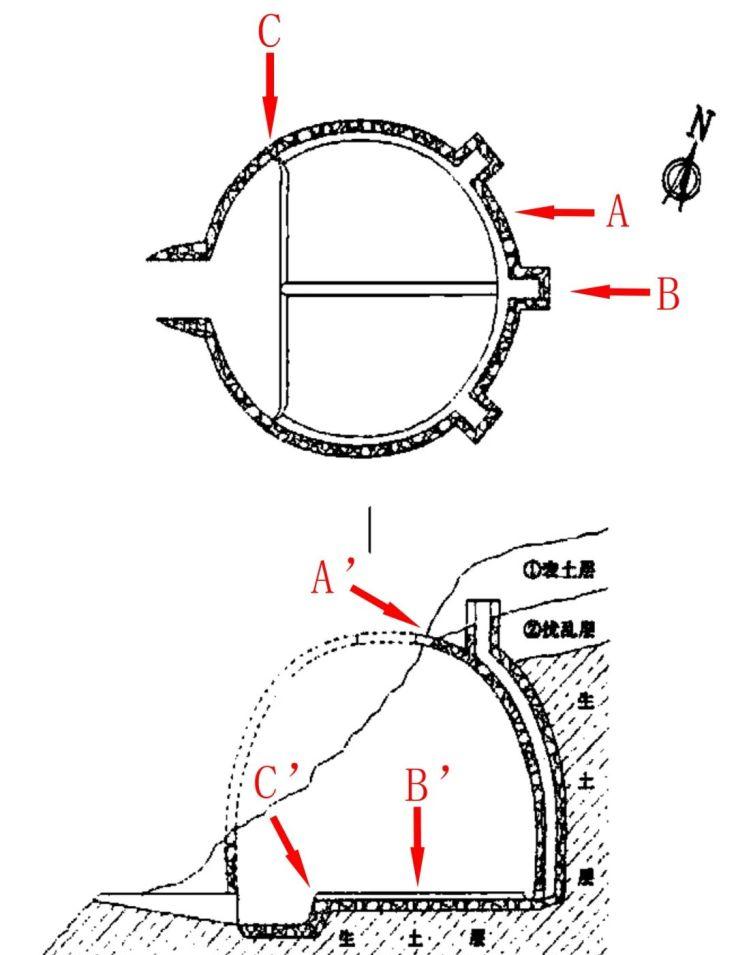
Figure 1
2. Y2 flat section of the ming dynasty official brick kiln site in JiangxiaMiaoshan, Wuhan City, Hubei Province (Figure 2)
In Figure 2, the plotter adopts the representation method of connecting a diagonal line to the bottom of the inner wall of the fire chamber at the end of the fire tunnel, which seems to be inappropriate. (The diagonal line is shown in figure 2 red arrows indicating the location) In addition, the drawing of the exhaust road floor plan and the cross-sectional view obviously do not correspond, and it is also debatable that only one chimney is drawn on the cross-section. This issue is discussed in detail in Section 3 of this article.

Figure 2
The author believes that such problems are due to the limited space of the kiln room by the plotter, and the site cannot accurately observe and measure the data, and it is difficult to accurately show the complex kiln structure. If the three-dimensional coordinate data of the kiln is collected on the spot, and then the anatomical observation is built in the computer software, such problems can be better solved.
02
Based on 3D modeling, the furnace line diagram is drawn
Next, the drawing work of the kiln slope archaeological site Y13 is used to introduce the basic process of drawing line drawings based on 3D modeling software.
The kiln site is located in Shunfu Village, Zhongfang Town, Zhongfang County, Huaihua City, and is the site of the official kiln fired by bricks of the Ming Dynasty city wall. Since May 2021, in order to cooperate with the construction of the industrial park in Huaihua High-tech Zone, the Hunan Provincial Institute of Cultural Relics and Archaeology has carried out rescue archaeological excavations at the kiln site. The clean-up of 20 brick kilns has been completed.
The Y13 is shaped as a semi-crypt type steamed bun kiln. The main part of the kiln is placed in situ in the soil slope. After simply trimming the fault by borrowing the mountain, dig deep into the kiln on the section. It is composed of four parts: kiln road, kiln door, fire chamber and kiln chamber. Among them, the kiln room is composed of kiln beds, fire channels and smoke extraction facilities. The inner wall of the kiln chamber and the chimney is reddish brown due to high temperature roasting, forming a plate of red burnt soil, which is very strong. The top of the kiln chamber has collapsed, and the arch can be seen, and it is speculated that it was a dome-shaped roof when it was installed. Between the kiln bed and the kiln door is the fire chamber, and the bottom surface of the fire chamber is relatively flat, lower than the kiln bed. The plan of the kiln chamber is circular, the bottom is flat, and the outside of the kiln bed has a large circle of fire channels that drill obliquely into the raw soil layer. There are regular discharge brick marks on the kiln bed and the green bricks on the back wall of the kiln room are connected, and several fire extraction channels should be built for the green bricks. The back chamber of the kiln is a single chimney structure, and the damage to the upper part of the chimney is not visible. Photos of the scene are shown in Figure 3:
Figure 3
The author judged on the spot that the kiln furnace structure is complex, the field drawing is difficult and inefficient, and the accuracy of the drawing is difficult to control. Therefore, it was decided to collect three-dimensional coordinate data on the site of the kiln, and use computer software indoors to model and draw the furnace line diagram. The workflow is as follows:
1. On-site surveying and mapping control points. First, several targets are placed on each side of the brick kiln, and then the RTK is used to map its three-dimensional coordinate data. This step is extremely important, and the purpose is to digitally informatize the kiln based on the National Geographic Coordinate System. Only by assigning all the point clouds of the brick kiln model to the real 3D coordinate information can it be called 3D modeling. Photographs of the site placement of targets are shown in Figure 4:
Figure 4
2. Take photos with digital cameras from multiple angles on the spot, and ensure that the photo overlap rate reaches more than 60%. Indoors, photos are imported into the Photoscan software to generate 3D models. The Y13 model is shown in Figure 5:
Figure 5
3. Export orthophoto images such as the top and section of the 3D model to the drawing software to draw the line diagram. The drawing software can be chosen by itself, and here the author uses Coreldraw software.
The author first exported a Y13 top orthophoto map and marked the scale bar in the PS software according to the pixel size, and then imported it into the Coreldraw software to draw. (Because the control points are based on the National Geographic Coordinate System mapping, the map is already due north-south.) The top orthophoto is shown in Figure 6:
Figure VI
The drawn plan of the kiln is shown in Figure 7:
Figure VII
The author then dissected the kiln roof from the maximum diameter of the furnace façade in the Photoloscan software and exported the kiln basemap. After superimposing the drawn plan line drawing with the kiln bottom photo in the Coreldraw software, it can be found that because the kiln roof of the mantou kiln is a dome structure, the kiln wall in the orthographic projection floor plan obscures many parts of the kiln room. These include: a small part of the perimeter of the kiln bed, the fire tunnel, a row of green bricks placed outside the fire tunnel at the back of the kiln chamber, and a pocket-shaped pit at the bottom of the smoke extraction facility. (See Figure 8)
Figure VIII
These occluded parts are difficult to measure accurately on the spot using traditional methods, and even some low and narrow spaces cannot be started, so many plotters often draw the fire path and the kiln wall with solid lines at the same time, although simple and clear, but ignore the characteristics of the dome-shaped kiln wall. As shown in Figure 2, this problem is obvious. The 3D model can be easily observed and accurately plotted by dissecting the 3D model from multiple angles in the computer software. After the interior structure of the kiln obscured by the kiln wall is drawn, the red dotted part of Figure 9 is completed.
Figure IX
Using the same method, the orthophomography of the cross-section and longitudinal profile of the furnace was dissected in the Photoscan software to complete the Y13 line diagram. See Figure 10:
Figure 10
03
Avoid the errors of traditional drawing through modeling
The problem of chimney performance in the sections of Figures 1 and 2 mentioned above is the example of Y52, an archaeological site on the slope of the kiln, which is also a three-chimney brick-making kiln.
It is not difficult to see from the orthophoto image of the longitudinal profile of the Y52 3D modeling of Figure 11 that the structure of the kiln chamber has been more intuitively displayed. The two visible chimneys on the profile are very clearly positioned, and their kiln bed countertops are tilted downward in the direction of the smoke extraction facility, which is easy to ignore when drawing on site. Obviously, through the observation of anatomical three-dimensional modeling, it is easier to compare and accurately draw the characteristics of the kiln structure.
Figure XI
Y52 line diagram (partial) see Figure XII:
Figure XII
As can be seen from Figure 9, the firing tunnel on the outside of the kiln bed should be obscured by the dome-shaped roof kiln wall. The cross-section of Figure II also clearly sees this, but the fire channel in the plan of Figure II is clearly visible, resulting in a flat section that does not correspond. And the two profiles in Figure 2 theoretically do not seem to be straight walls. The correct representation should be shown in Figure 10.
In Figures 1 and 2, the performance of the firing tunnel on the longitudinal section of the outer side of the kiln bed, taking the kiln slope archaeological site Y13 as an example, it can be seen through the photos that the extraction tunnel is excavated from the connection between the kiln bed and the fire chamber. The outer side is inclined into the raw soil layer, and the kiln wall side is higher than the kiln bed plane. And the inner wall of the fire chamber without a fire channel is smooth and flat, and there is no obvious polyline. In Figure 2, the plotter uses a diagonal line to connect the dentist to the bottom of the fire chamber, although the line diagram looks more beautiful and not obtrusive. But in practice, this diagonal line should not exist, and this artificially added line is easy to cause misunderstanding among the viewer.
The photo of the Y13 fire tunnel is shown in Figure XIII:
Figure XIII
Through the anatomical analysis of the Y13 three-dimensional modeling, the author believes that the performance method of the extraction tunnel in the cross-sectional view should be the part pointed by the red arrow in Figure 14.
Figure XIV
Of course, this method of expression is only the author's personal experience, not the best solution. I hope that colleagues can put forward valuable opinions and discuss together.
In summary, it can be seen that the line chart structure based on 3D modeling is basically accurate, avoiding many problems that may occur in traditional drawings.
04
Conclusion
Dimensional measurements such as complex brick kiln fire escapes, chimney walls, and pocket pits at the bottom of the smoke extraction facility at the back of the narrow kiln chamber are all old problems in field drawing, which are now solved by 3D modeling software. The author believes that the mapping of the remains of archaeological sites, in addition to aesthetics, is more important than efficiency and accuracy. In the past, it was often necessary to draw a few hours or even a dozen hours of complex structural relics units, but now it takes only about half an hour to collect three-dimensional modeling data on site, which greatly improves the excavation efficiency of archaeological sites. Moreover, the computer software is used to draw accurately and modify it in the later stage. At the same time, the three-dimensional coordinate data of the relic units is also preserved to the greatest extent. It's a lot of things.
In today's digital archaeological sites, I believe that the instruments and equipment of major construction sites are relatively complete. For structurally complex relic units, computer drawings based on 3D modeling processing are bound to be used more and more by archaeologists as an aid and supplement to traditional hand-drawn drawings. The author's purpose of this article is to throw bricks and jade and discuss with colleagues in the archaeological community. There are inevitably many errors and omissions in the text, please criticize and correct.
Reprinted from Hunan Archaeology