三層架構架構:
接入層:提供端口的密度,用于使用者終端的接入。一般使用二層交換機、AP等裝置。
彙聚層(分布層):流量的集合處。可以用到的技術有:DHCP / VLAN / STP / HSRP / VRRP / channel / QOS / ACL…
核心層:使用NAT實作内網與公網之間的通路。能夠進行高速路由轉發。
三層架構的核心:
備援—備份。 線路備份、裝置備份、網關備份、UPS(電源)備份。
注:UPS(電源)備份不屬于技術。裝置若存在雙電源口,将兩根電源查到不同的供電處即可實作電源備份。
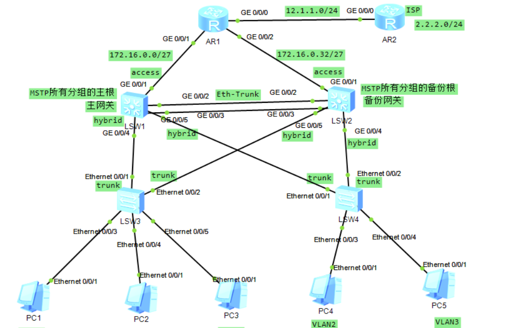
三層架構案例:
拓撲圖:
要求:
1:ISP隻能配置公有IP,不得再進行其他任何配置。
2:所有PC通過DHCP擷取IP位址。
3:STP-MSTP合理分組,VLAN—混用中繼和混雜模式。
4:内網IP位址基于172.16.0.0/16合理配置設定。
5:ISP Telnet 登入R1的公有IP位址,實際登入到SW1上。
6:正常所有PC均可以通路ISP環回。當随機在SW1和SW2中關閉一台裝置時,PC依然可以正常通路ISP。
配置與思路:
1:劃分IP位址。
R1與R2之間公有位址使用12.1.1.0/24網段,ISP(R2)環回位址為2.2.2.0/24.
内網IP位址:
172.16.0.0/27----R1與SW1之間
    172.16.0.32/27----R1與SW2之間

    172.16.0.64/27----VLAN1
    172.16.0.66/27----VLAN1的網關

    172.16.0.96/27----VLAN2
    172.16.0.98/27----VLAN2的網關

    172.16.0.128/27----VLAN3
    172.16.0.130/27----VLAN3的網關
2:配置
1>:在SW1上配置DHCP,并且作為主網關使所有PC可以通過DHCP擷取IP位址
SW1:
<Huawei>system-view
Enter system view, return user view with Ctrl+Z.
[Huawei]sy
[Huawei]sysname sw1
[sw1]
[sw1]vlan 2
[sw1-vlan2]quit
[sw1]vlan 3
[sw1-vlan3]quit
[sw1]interface Vlanif 1
[sw1-Vlanif1]ip address 172.16.0.65 27
[sw1-Vlanif1]vrrp vrid 1 virtual-ip 172.16.0.66
[sw1-Vlanif1]vrrp vrid 1 priority 120
[sw1-Vlanif1]vrrp vrid 1 preempt-mode timer delay 20
[sw1-Vlanif1]vrrp vrid 1 track interface GigabitEthernet 0/0/1 reduced 30
[sw1-Vlanif1]
[sw1-Vlanif1]quit
[sw1]dhcp enable
[sw1]ip pool 1
[sw1-ip-pool-1]network 172.16.0.64 mask 27
[sw1-ip-pool-1]gateway-list  172.16.0.66
[sw1-ip-pool-1]dns-list 8.8.8.8
[sw1-ip-pool-1]quit
[sw1]interface Vlanif 1
[sw1-Vlanif1]dhcp select global
[sw1-Vlanif1]quit
[sw1]
[sw1]interface Vlanif 2
[sw1-Vlanif2]ip add
[sw1-Vlanif2]ip address 172.16.0.97 27
[sw1-Vlanif2]vrrp vrid 2 virtual-ip 172.16.0.98
[sw1-Vlanif2]vrrp vrid 2 priority 120
[sw1-Vlanif2]vrrp vrid 2 preempt-mode timer delay 20
[sw1-Vlanif2]vrrp vrid 2 track interface GigabitEthernet 0/0/1 reduced 30
[sw1-Vlanif2]quit
[sw1]ip pool 2
[sw1-ip-pool-2]network 172.16.0.96 mask 27
[sw1-ip-pool-2]gateway-list  172.16.0.98
[sw1-ip-pool-2]dns-list 8.8.8.8
[sw1-ip-pool-2]quit
[sw1]
[sw1]interface Vlanif 2
[sw1-Vlanif2]dhcp select global
[sw1-Vlanif2]quit
[sw1]interface Vlanif 3
[sw1-Vlanif3]ip address 172.16.0.129 27
[sw1-Vlanif3]vrrp vrid 3 virtual-ip 172.16.0.130
[sw1-Vlanif3]vrrp vrid 3 priority 120
[sw1-Vlanif3]vrrp vrid 3 preempt-mode timer delay 20
[sw1-Vlanif3]vrrp vrid 3 track interface GigabitEthernet 0/0/1 reduced 30
[sw1-Vlanif3]quit
[sw1]ip pool 3
[sw1-ip-pool-3]network 172.16.0.128 mask 27
[sw1-ip-pool-3]gateway-list 172.16.0.130
[sw1-ip-pool-3]dns-list 8.8.8.8
[sw1-ip-pool-3]quit
[sw1]interface Vlanif 3
[sw1-Vlanif3]dhcp select global
[sw1-Vlanif3]quit
[sw1]interface GigabitEthernet 0/0/4
[sw1-GigabitEthernet0/0/4]port hybrid tagged vlan 1 to 3
[sw1-GigabitEthernet0/0/4]quit
[sw1]interface GigabitEthernet 0/0/5
[sw1-GigabitEthernet0/0/5]port hybrid tagged vlan 1 to 3
[sw1-GigabitEthernet0/0/5]quit
[sw1]
SW3:
<Huawei>system-view
[Huawei]sysname sw3
[sw3]interface Eth0/0/1
[sw3-Ethernet0/0/1]port link-type trunk
[sw3-Ethernet0/0/1]port trunk allow-pass vlan 1 to 3
[sw3-Ethernet0/0/1]quit
[sw3]vlan 2
[sw3-vlan2]quit
[sw3]vlan 3
[sw3-vlan3]quit
[sw3]port-group group-member Ethernet 0/0/3 to Ethernet 0/0/5
[sw3-port-group]port link-type access
[sw3-port-group]quit
[sw3]interface Eth0/0/4
[sw3-Ethernet0/0/4]port default vlan 2
[sw3-Ethernet0/0/4]quit
[sw3]interface Eth0/0/5
[sw3-Ethernet0/0/5]port default vlan 3
[sw3-Ethernet0/0/5]quit
[sw3]
SW4:
<Huawei>system-view
[Huawei]sysname sw4
[sw4]interface Eth0/0/1
[sw4-Ethernet0/0/1]port link-type trunk
[sw4-Ethernet0/0/1]port trunk allow-pass vlan 1 to 3
[sw4-Ethernet0/0/1]quit
[sw4]vlan 2
[sw4-vlan2]quit
[sw4]vlan 3
[sw4-vlan3]quit
[sw4]port-group group-member Ethernet 0/0/3 to Ethernet 0/0/4
[sw4-port-group]port link-type access
[sw4-port-group]quit
[sw4]interface Eth0/0/3
[sw4-Ethernet0/0/3]port default vlan 2
[sw4-Ethernet0/0/3]quit
[sw4]interface Eth0/0/4
[sw4-Ethernet0/0/4]port default vlan 3
[sw4-Ethernet0/0/4]quit
[sw4]
測試:
PC1:

PC2:
PC3:
PC4:
PC5:
測試得出所有PC将SW1作為網關通過DHCP可以正常擷取IP位址。
2>:在SW2上進行配置,使SW2作為SW2的備份網關。并且SW1與SW2之間的鍊路進行疊加。
SW2:
<Huawei>system-view
[Huawei]sysname sw2
[sw2]vlan 2
[sw2-vlan2]quit
[sw2]vlan 3
[sw2-vlan3]quit
[sw2]interface Vlanif 1
[sw2-Vlanif1]ip address 172.16.0.67 27
[sw2-Vlanif1]vrrp vrid 1 virtual-ip 172.16.0.66
[sw2-Vlanif1]quit
[sw2]dhcp enable
[sw2]ip pool 1
[sw2-ip-pool-1]network 172.16.0.64 mask 27
[sw2-ip-pool-1]gateway-list 172.16.0.66
[sw2-ip-pool-1]dns-list 8.8.8.8
[sw2-ip-pool-1]quit
[sw2]interface Vlanif 1
[sw2-Vlanif1]dhcp select global
[sw2-Vlanif1]quit
[sw2]
[sw2]interface Vlanif 2
[sw2-Vlanif2]ip address 172.16.0.99 27
[sw2-Vlanif2]vrrp vrid 2 virtual-ip 172.16.0.98
[sw2-Vlanif2]quit
[sw2]ip pool 2
[sw2-ip-pool-2]network 172.16.0.96 mask 27
[sw2-ip-pool-2]gateway-list 172.16.0.98
[sw2-ip-pool-2]dns-list 8.8.8.8
[sw2-ip-pool-2]quit
[sw2]interface Vlanif 2
[sw2-Vlanif2]dhcp select global
[sw2-Vlanif2]quit
[sw2]
[sw2]interface Vlanif 3
[sw2-Vlanif3]ip address 172.16.0.131 27
[sw2-Vlanif3]vrrp vrid 3 virtual-ip 172.16.0.130
[sw2-Vlanif3]quit
[sw2]ip pool 3
[sw2-ip-pool-3]network 172.16.0.128 mask 27
[sw2-ip-pool-3]gateway-list  172.16.0.130
[sw2-ip-pool-3]dns-list 8.8.8.8
[sw2-ip-pool-3]quit
[sw2]interface Vlanif 3
[sw2-Vlanif3]dhcp select global
[sw2-Vlanif3]quit
[sw2]interface GigabitEthernet 0/0/5
[sw2-GigabitEthernet0/0/5]port hybrid tagged vlan 1 to 3
[sw2-GigabitEthernet0/0/5]quit
[sw2]interface GigabitEthernet 0/0/4
[sw2-GigabitEthernet0/0/4]port hybrid tagged vlan 1 to 3
[sw2-GigabitEthernet0/0/4]quit
SW4:
[sw4]interface Eth0/0/2
[sw4-Ethernet0/0/2]port link-type trunk
[sw4-Ethernet0/0/2]port trunk allow-pass vlan 1 to 3
[sw4-Ethernet0/0/2]quit
SW3:
[sw3]interface Eth0/0/2
[sw3-Ethernet0/0/2]port link-type trunk
[sw3-Ethernet0/0/2]port trunk allow-pass vlan 1 to 3
[sw3-Ethernet0/0/2]quit
鍊路疊加:
鍊路疊加的要求:
1、通道的對端必須為同一台裝置;
2、通道的所有實體接口應該具有相同的速率、雙工模式;相同的類型,相同的vlan允許清單;
SW1:
[sw1]interface Eth-Trunk 0
[sw1-Eth-Trunk0]quit
[sw1]interface GigabitEthernet 0/0/2
[sw1-GigabitEthernet0/0/2]eth-trunk 0
[sw1-GigabitEthernet0/0/2]quit
[sw1]interface GigabitEthernet 0/0/3
[sw1-GigabitEthernet0/0/3]eth-trunk 0
[sw1-GigabitEthernet0/0/3]quit
[sw1]interface Eth-Trunk 0
[sw1-Eth-Trunk0]port link-type hybrid
[sw1-Eth-Trunk0]port hybrid tagged vlan 1 to 3
[sw1-Eth-Trunk0]quit
SW2:
[sw2]interface Eth-Trunk 0
[sw2-Eth-Trunk0]quit
[sw2]interface GigabitEthernet 0/0/2
[sw2-GigabitEthernet0/0/2]eth-trunk 0
[sw2-GigabitEthernet0/0/2]quit
[sw2]interface GigabitEthernet 0/0/3
[sw2-GigabitEthernet0/0/3]eth-trunk 0
[sw2-GigabitEthernet0/0/3]quit
[sw2]interface Eth-Trunk 0
[sw2-Eth-Trunk0]port link-type hybrid
[sw2-Eth-Trunk0]port hybrid tagged vlan 1 to 3
[sw2-Eth-Trunk0]quit
3>:配置MSTP,VLAN1劃入組1,VLAN2、3劃入組2,且主根為SW1,備份根為SW2。
SW1:
[sw1]stp mode mstp
[sw1]stp enable
[sw1]stp region-configuration
[sw1-mst-region]region-name a
[sw1-mst-region]instance 1 vlan 1
[sw1-mst-region]instance 2 vlan 2 to 3
[sw1-mst-region]active region-configuration
[sw1-mst-region]quit
[sw1]stp instance 1 root primary
[sw1]stp instance 2 root  primary
SW2:
[sw2]stp mode mstp
[sw2]stp enable
[sw2]stp region-configuration
[sw2-mst-region]region-name a
[sw2-mst-region]instance 1 vlan 1
[sw2-mst-region]instance 2 vlan 2 to 3
[sw2-mst-region]active region-configuration
[sw2-mst-region]quit
[sw2]stp instance 1 root secondary
[sw2]stp instance 2 root secondary
SW3:
[sw3]stp mode mstp
[sw3]stp enable
[sw3]stp region-configuration
[sw3-mst-region]region-name a
[sw3-mst-region]instance 1 vlan 1
[sw3-mst-region]instance 2 vlan 2 to 3
[sw3-mst-region]active region-configuration
[sw3-mst-region]quit
SW4:
[sw4]stp mode mstp
[sw4]stp enable
[sw4]stp region-configuration
[sw4-mst-region]region-name a
[sw4-mst-region]instance 1 vlan 1
[sw4-mst-region]instance 2 vlan 2 to 3
[sw4-mst-region]active region-configuration
[sw4-mst-region]quit
4>:在SW1和SW2上給實體接口配置IP位址來讓SW1和SW2能與R1進行通路。
注:由于ENSP上的三層交換機在模拟器上不能直接給實體接口配置IP位址(真機可以),是以需要換思路:将需要配置IP位址的接口改為access模式并且劃分到一個VLAN中,然後給該VLAN配置IP位址即可達到相同的效果。
SW1:
[sw1]vlan 10
[sw1-vlan10]quit
[sw1]interface GigabitEthernet 0/0/1
[sw1-GigabitEthernet0/0/1]port link-type access
[sw1-GigabitEthernet0/0/1]port default vlan 10
[sw1-GigabitEthernet0/0/1]quit
[sw1]interface Vlanif 10
[sw1-Vlanif10]ip address 172.16.0.2 27
[sw1-Vlanif10]quit
SW2:
[sw2]vlan 10
[sw2-vlan10]
[sw2-vlan10]quit
[sw2]interface GigabitEthernet 0/0/1
[sw2-GigabitEthernet0/0/1]port link-type access
[sw2-GigabitEthernet0/0/1]port default vlan 10
[sw2-GigabitEthernet0/0/1]quit
[sw2]interface Vlanif 10
[sw2-Vlanif10]ip address 172.16.0.34 27
[sw2-Vlanif10]quit
R1:
[r1]interface GigabitEthernet 0/0/1
[r1-GigabitEthernet0/0/1]ip address 172.16.0.1 27
[r1-GigabitEthernet0/0/1]quit
[r1]interface GigabitEthernet 0/0/2
[r1-GigabitEthernet0/0/2]ip address 172.16.0.33 27
[r1-GigabitEthernet0/0/2]quit
測試R1與SW1和SW2實體接口能否正常通路:
5>:在R1上配置VLAN1、2、3的靜态路由,下一跳分别為SW1和SW2連接配接R1的實體接口,且下一跳為SW2連接配接R1的接口的路由為備份路由,優先級數值較大。
R1:
[r1]ip route-static 172.16.0.64 27 172.16.0.2
[r1]ip route-static 172.16.0.96 27 172.16.0.2
[r1]ip route-static 172.16.0.128 27 172.16.0.2
[r1]ip route-static 172.16.0.64 27 172.16.0.34 preference 61
[r1]ip route-static 172.16.0.96 27 172.16.0.34 preference 61
[r1]ip route-static 172.16.0.128 27 172.16.0.34 preference 61
6>:在R1和R2上配置公網位址,并通過NAT實作所有PC可以通路ISP環回
R1:
[r1]interface GigabitEthernet 0/0/0
[r1-GigabitEthernet0/0/0]ip address 12.1.1.1 24
[r1-GigabitEthernet0/0/0]quit
[r1]acl 2000
[r1-acl-basic-2000]rule 5 permit source 172.16.0.0 0.0.0.255
[r1]interface GigabitEthernet 0/0/0
[r1-GigabitEthernet0/0/0]nat outbound 2000
[r1-GigabitEthernet0/0/0]quit
[r1]ip route-static 0.0.0.0 0 12.1.1.2
SW1:
[sw1]ip route-static 0.0.0.0 0 172.16.0.1
SW2:
[sw2]ip route-static 0.0.0.0 0 172.16.0.33
測試所有PC能否正常通路ISP環回:
PC1:
PC2:
PC3:
PC4:
PC5:
7>:在SW1上開啟telnet服務,并在R1上配置端口映射。
SW1:
[sw1]user-interface vty 0 4
[sw1-ui-vty0-4]authentication-mode password
[sw1-ui-vty0-4]user privilege level 15
[sw1-ui-vty0-4]set authentication password simple huawei123
[sw1-ui-vty0-4]quit
R1:
[r1]interface GigabitEthernet 0/0/0
[r1-GigabitEthernet0/0/0]nat server protocol tcp global current-interface telnet
 inside 172.16.0.2 telnet
Warning:The port 23 is well-known port. If you continue it may cause function fa
ilure.
Are you sure to continue?[Y/N]:y
[r1-GigabitEthernet0/0/0]
在R2上進行測試:
<r2>telnet 12.1.1.1
  Press CTRL_] to quit telnet mode
  Trying 12.1.1.1 ...
  Connected to 12.1.1.1 ...


Login authentication


Password:
Info: The max number of VTY users is 5, and the number
      of current VTY users on line is 1.
      The current login time is 2019-11-14 21:54:52.
<sw1>sy
<sw1>system-view
Enter system view, return user view with Ctrl+Z.
[sw1]
[sw1]
測試:将SW1裝置關閉,再次測試PC能否正常通路ISP環回。
PC1:
PC2:
PC3:
PC4:
PC5:
3:MSTP測試
對于生成樹而言,根網橋為SW1,則為避免環路會阻塞SW4連接配接3号線的端口。PC4、5擷取DHCP是通過SW4連接配接2号線的端口進行擷取的(主網關正常的情況下)。此時斷開2号線,測試PC4、5能否正常通路 ISP環回。
SW4:
[sw4]interface Eth0/0/1
[sw4-Ethernet0/0/1]shutdown
PC4:
PC5:
對于生成樹組1而言,正常情況下會阻塞SW3連接配接2号線的端口(主網關正常),PC1通過SW3連接配接3号線的端口擷取IP位址。将SW3連接配接3号線的端口關閉,再次測試PC1能否正常通路ISP環回。
SW3:
[sw3]interface Eth0/0/1
[sw3-Ethernet0/0/1]shutdown
PC1:
至此,ENSP實作企業網三層架構全部完成。但缺點是接入層的PC沒有做線路備援,沒有達到高可靠性。