An overview of the overall idea of AUTOSAR
First, the overall overview
AUTOSAR, short for Automotive Open System Architecture, is an alliance dedicated to developing software standards for automotive electronics. AUTOSAR is a combination of global automakers, component suppliers and other electronic, semiconductor and software systems companies, with members maintaining development partnerships. Since 2003, partner companies have worked together to develop an open and standardized software architecture for the automotive industry. AutoSAR is an architecture that facilitates the exchange and update of vehicle electronic system software, and provides a basis for efficient management of increasingly complex vehicle electronic and software systems. In addition, AUTOSAR improves cost efficiency while ensuring the quality of product and service.
The vehicle software system can deeply manage the diagnostic functions of the vehicle network, system memory and bus through the AUTOSAR architecture, and its emergence is conducive to the update and exchange of the vehicle electronic system software, and improves the reliability and stability of the system. At present, the tool and software vendors that support the AUTOSAR standard have launched corresponding products, providing requirements management, system description, software component algorithm model verification, software construction algorithm modeling, software component code generation, RTE generation, ECU configuration, and basic software and operating system services, helping OEMs achieve a seamless system software architecture development process.
There are three main objectives of the AUTOSAR program:
1) Establish a layered software architecture independent of the hardware;
2) Provide methodologies for implementing applications, including developing a seamless software architecture stacking process and integrating application software into ecus;
3) Formulate various vehicle application interface specifications as application software integration standards so that software components can be reused on different automotive platforms.
Second, the hierarchical overview
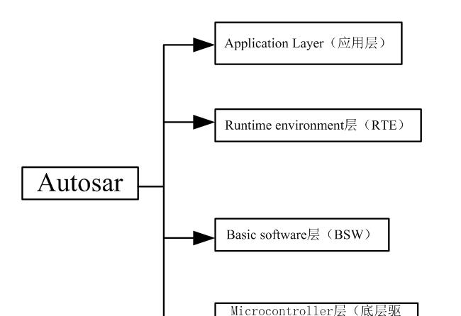
The overall autosar framework is designed in a hierarchical manner, bounded by the middleware RTE (Runtime Environment), separating the upper application layer from the underlying basic software. Figure 1 shows the AUTOSAR architecture layering standard.

Figure 1 THE AUTOSAR architecture layering standard
1. Application Layer
The functions in the application layer are implemented by each software component SWC (software component), which encapsulates some or all of the automotive electronic functions, including the implementation of its specific functions and corresponding descriptions, such as controlling the operation of headlights, air conditioners and other components, but is not connected to the automotive hardware system.
1) Software component SWC (software component)
The software component SWC (software component) is composed of the smallest logical unit of the Atomic component. The atomic component minimum logical units are Applied, Sensor/actuator and two types. Among them, Application is an algorithm implementation type that can be freely mapped on each ECU; Sensor/actuator is an I/O port type for Application to be used to bind to the ECU, but it cannot be freely mapped on each ECU like Application. The logical set of several SWCs is combined into Position. Figure 2 shows an example of swc composition.
Figure 2
2) Port Ports
Ports is used to communicate with other SWCs. Communication content is divided into Data elements and operations. Where, Data elements communicate in Thender/Receiver; operations communicate in The Client/Server. Figure 3 is the communication method
Figure 3
Sender/Receiver is used to transmit data and has a communication port that can contain a variety of data types. But if a data type is to be transmitted over a bus, it must correspond to a signal that can be either a simple integer or a complex array( record). Communication mode: 1:n or n:1
Figure 4
Client—The client/server port (Client/Serverr) is used to provide Operation services, with a client-server port can contain a variety of Operation and synchronous or asynchronous communication characteristics, a client-server port can contain multiple Operations operations, and Operations operations can also be invoked individually. Communication mode: 1:n or n:1.
Figure 5
3) Runnables entities
Runnablesentities, or Runnables for short. A runnable entity contains an actually implemented function, which can be a concrete logical algorithm or a real operation. Runnable entities are called periodically by RTE or event triggers, such as when data is received.
Figure 6
2、Runtime environment层 (RTE)
The middleware part provides communication means for the application layer, where communication is a generalized communication, which can be understood as an interface, and there are two kinds of information interaction between the application layer and other software bodies, the first is the information interaction between different modules in the application layer; the second is the information interaction between the application layer module and the underlying software. RTE is the hub for the interfaces used by these interactions, and it summarizes all the interfaces that need to interact with the outside of the software body. In a sense, designing a system that complies with AUTOSAR is actually designing an RTE.
Communication between SW-C is done by calling RTE API functions rather than implementing them directly, and is under the management and control of RTE. Each API follows a uniform naming convention and is only related to the description of the software component itself. The specific communication implementation depends on the system design and configuration, which is automatically generated by the RTE Generator provided by the tool vendor.
During the design and development phase, a new concept was introduced at the communication level of software components, the Virtual Functional Bus VFB. It is an abstraction of all the communication mechanisms of AUTOSAR, using VFB, the development engineer will abstract the communication details of the software components, only need to be described through the interface defined by AUTOSAR, that is, to achieve communication between software components and other components and hardware, and even data transmission within the ECU or between other ECUs.
Figure 7
As you can see from the diagram, there are three interface descriptions, and let's first look at the differences between these three interfaces from a definitional point of view.
1. StandardizedInterface (standard interface): The standard interface is an interface that is standardized in the AUTOSAR standard, but does not use autosar interface technology, and the standard interface is usually used in the communication between software modules inside an ECU and cannot be used for network communication.
2. StandardizedAUTOSAR Interface (Standard AUTOSAR Interface): The standard AUTOSAR interface is an interface standardized in the AUTOSAR standard using AUTOSAR interface technology, the syntax and semantics of such an interface are specified, such an interface is usually used in autosar services, such an interface is the basic software service provided to the application.
3. AUTOSARInterface (AUTOSAR interface): The AUTOSAR interface defines the way of interaction between the software module and the BSW module (only IO abstraction and complex drive), the AUTOSAR interface is in the form of port, AUTOSAR unifies the communication and network communication interfaces used within the ECU.
From the above definition, we can see that different interfaces use different scenarios, and different module interactions use different interfaces. What is the practical point of such a definition other than categorizing interfaces? From the perspective of practical use, the first and second types of interfaces are all semantically standardized interfaces, that is, the number of interface functions, the name of the function, the name and quantity of the function parameters, the function function, and the return value of the function have been defined in the standard. Although the content algorithms of different companies' software are different when implementing these interfaces, their appearance and function are consistent, and the interface definition can be found in the AUTOSAR specification document. The third type of interface, AUTOSAR only specifies a simple naming convention, this type of interface height and application-related, such as BCU control headlights open interface can be Rte_Call_RPort_BeamLight_SetDigOut can also be Rte_Call_RPort_HeaderLight_Output, the company can define itself, and for example, the instrument wants to get the speed from the CAN bus, The interfaces can be Rte_IRead_RE_Test_RPort_Speed_uint8 or Rte_IRead_Test_RE_RPort_Spd_uint8, and these interfaces must interact via RTE.
Figure 8
3、Basic software层(BSW)
Although there are various ECU in the car, they have a variety of functions, but the basic services required to achieve these functions can be abstracted, such as IO operations, AD operations, diagnostics, CAN communication, operating systems, etc., nothing more than different ECU functions, the OPERATION OF IO, AD represent different meanings, the RECEIVED messages sent represent different meanings, and the task cycle priority scheduled by the operating system is different. These basic services that can be abstracted out are called base software. Depending on the functionality, the underlying software can continue to be subdivided into four parts, namely the Service Layer, the ECU Abstract Layer, the ComplexDriver, and the MCAL (Microcontroller Absstraction Layer), and the degree of interdependencies between the four parts is not the same.
Service layer (Service Layer), this layer of basic software provides automotive ECU non-application-related services, including OS, network communication, memory management (NVRAM), diagnostics (UDS, fault management, etc.), ECU state management module, etc., they provide auxiliary support for the application layer functions of the ECU, this layer of software is also very similar in different areas of ECUs, such as different ECU OS task cycles and priorities are different, The partitions of NVRAM in different ECUs are different, and the contents of the storage are different.
ECU abstract layer (ECU Abstract Layer), this layer of software provides ECU application-related services, it is an abstraction of an ECU, it includes all the ECU input and output, such as AD, DIO, PWM, etc., this layer of software directly implements the application layer function of the ECU, can read the sensor state, can control the actuator output, different areas of the ECU will be very different.
MCAL (Microcontroller Absstraction Layer), this layer of software is the abstraction of the master control chip used in the ECU, it is closely related to the implementation of the chip, is the lowest part of the ECU software, directly interact with the master chip and peripheral chip, its role is to abstract the functions provided by the chip into interfaces, and then provide these interfaces to the upper service layer / ECU abstraction layer to use.
Complex drivers (Complex Drivers), there are some areas of the automotive ECU ECU will process quite complex hardware signals, perform quite complex hardware actions, such as engine control, ABS, etc., these function-related software is difficult to abstract out for all automotive ECUs, it is closely related to the application of ECU and the hardware used in ECU, belongs to the AUTOSAR architecture in different ECUs can not be ported parts.
Figure 9
Figure 10 is a description of the various submodules in the BSW layer.
Figure 10
4. Microcontroller layer
The underlying drive layer is provided by the chip manufacturer.
3. Development tools
The above figure shows the development tools that can be used in the autosar development process stage and each stage. Judging from online research, Vector and EB have a complete set of development tool chains. Among them, the DaVinciDeveloper and DaVinci ConfiguratorPro development tools in Vector are more commonly used, and it is recommended to use Vector to develop the toolchain.
From the perspective of the development process, each stage of development has its own development tools:
1) The system design stage is the demand development and system function design, using preevision development tools (price consultation does not return to the email);
2) SWC functional software development stage, that is, ECU function description, using DaVinciDeveloper developer; (price consultation did not return to the email);
3) BSW basic software and RTE design, using DaVinciConfigurator Pro to open the tool (price inquiry did not reply to the email);
4) Header file and C code using MATLAB · Simulink tools are automatically generated. (Pirated)
The image above shows the functional components used by Vector to develop AutoSar, where the red font is the component that comes with the Vector toolchain. According to the needs, OS, SYS, DIAG, MEM, COM, CAN, FR, ETH, MCAL components are tentatively required, and the price is in consultation.
The black font is provided by the underlying hardware vendor. It has been inquired that the price of the bottom drive of Renesas suppliers is $20K.
Fourth, the development process
MATLAB· Simulink and Real-TimeWorkshop Embedded Coder's code generation of the AUTOSAR standard is a transparent and intuitive process that supports two different workflows: top-down and bottom-up. We take a top-down approach to development.
From the top down, from the architecture model to autosar SC. In a top-down development process, systems engineers use architecture generation tools such as davinci tool suites to design the vehicle ECU network. Of course, engineers can also use other architectural design tools. The architecture software outputs an XML description of the corresponding component, which contains some necessary information about the component such as runnables, interfaces, data types, and so on. Matlab software can use the XML files generated by the architecture software to automatically create the Simulink architecture model, which contains the interface modules and the corresponding Autosar-related settings. The system engineer can then refine the internal control module on the basis of the framework model.