所謂"blend",英文解釋為“vt. 混合vi. 混合;協調n. 混合;摻合物”這裡應該了解為是圖像資料的融合。這是“識别->對準->融合”的最後一步。融合是決定拼接品質的關鍵一步,一方面它決定于圖像對準的品質,一方面它本身的也直接對拼接的最終結果負責。
最簡單和便于了解的融合為liner,正好借這個例子來說明說明是融合,簡單的說,就是在融合的區域……(這個地方引用相關資料)liner在opencv中沒有實作,但是本身簡單有效,對于要求不是很高的情況可以使用,這裡給出函數(再做相關解釋)
#pragma region mulitStitch
/*----------------------------
* 功|能 : 多圖比對
*----------------------------
* 函數y : MulitMatch
* 通路 : private
* 傳回 : void
*
* 參數y : matinput [in] 全部需要a比對圖的vector
* 參數y : matloc1 [ot] 所有D比對中D對應|于第一圖的結果向量
* 參數y : matloc1 [ot] 所有D比對中D對應|于第二t圖的結果向量
* 參數y : match_method [in] 比對方法
*/
void MulitMatch(deque<Mat>& matinput,deque<Point>& matloc1,deque<Point>& matloc2, int match_method)
{
Mat img_display1;Mat img_display2;
Point matchLoc1;Point matchLoc2;
for (int i =0;i<matinput.size()-1;i++)
{
//拷貝副本
img_display1 = matinput[i];
img_display2 = matinput[i+1];
//以中D心區域為aroi
// Mat imagetmp (img_display1, Rect(img_display1.rows/2, img_display1.cols/2, 10, 10) );//11:44:02
Mat imagetmp (img_display1, Rect(960,240, 10, 10) );//11:44:02
int result_cols = img_display1.cols - imagetmp.cols + 1;
int result_rows = img_display1.rows - imagetmp.rows + 1;
Mat imagematch;
imagematch.create( result_cols, result_rows, CV_32FC1 );
/// 進行D比對和标準化
//比對1
matchTemplate( img_display1, imagetmp, imagematch, match_method );
normalize( imagematch, imagematch, 0, 1, NORM_MINMAX, -1, Mat() );
double minVal; double maxVal;
Point minLoc; Point maxLoc;
minMaxLoc( imagematch, &minVal, &maxVal, &minLoc, &maxLoc, Mat() );
//智能判D斷,這a裡的matchLoc就是最佳比對點
if( match_method == CV_TM_SQDIFF || match_method == CV_TM_SQDIFF_NORMED )
{ matchLoc1 = minLoc; }
else
{ matchLoc1 = maxLoc; }
matloc1.push_back(matchLoc1); //加入序列D
//比對2
matchTemplate( img_display2, imagetmp, imagematch, match_method );
{ matchLoc2 = minLoc; }
{ matchLoc2 = maxLoc; }
matloc2.push_back(matchLoc2); //加入序列D
}
}
* 功|能 : 多圖對準
* 函數y : MulitAlign
* 傳回 : Mat
Mat MulitAlign(deque<Mat>& matinput,deque<Point>& matloc1,deque<Point>& matloc2)
{
Mat outImage; //待y輸出圖檔
//計算圖檔大小
int nr = matinput[0].rows;
int nl = matinput[0].cols*matinput[0].channels();
int ioffset = 0;int ioffsetdetail = 0;
//計算offset
for (int i =0;i<matloc1.size()-1;i++)
{
ioffset = ioffset+matloc1[i].y- matloc2[i].y;
}
outImage.create( matinput[0].rows+ioffset, matinput[0].cols, matinput[0].type());
for (int i=0;i<matloc1.size()-1;i++)
if (i == 0)//如果第一彈
{
for (int a=0;a<nr;a++) //第一圖
{
const uchar* inData=matinput[0].ptr<uchar>(a);
uchar* outData=outImage.ptr<uchar>(a);
for(int j=0;j<nl;j++)
{
outData[j]=inData[j];
}
}
for (int b=0;b<nr;b++) //第二t圖
const uchar* inData=matinput[1].ptr<uchar>(b);
uchar* outData=outImage.ptr<uchar>(b+matloc1[0].y-matloc2[0].y);
for(int j=0;j<nl;j++)
{
outData[j]=inData[j];
}
}
ioffsetdetail += matloc1[0].y-matloc2[0].y;
}
else//如果不是第一彈
for (int b=0;b<nr;b++)
const uchar* inData=matinput[i+1].ptr<uchar>(b);
uchar* outData=outImage.ptr<uchar>(b+ioffsetdetail+matloc1[i].y-matloc2[i].y);
ioffsetdetail += matloc1[i+1].y-matloc2[i].y;
}
return outImage;
* 功|能 : 多圖融合
* 函數y : MulitBlend
* 傳回 : Mat&
* 參數y : matinput [in] 圖檔輸入序列D
* 參數y : imagesrc [in] 已經-對準的圖檔
* 參數y : matloc1 [in] 第一圖比對位置
* 參數y : matloc2 [in] 第二t圖比對位置
Mat MulitBlend(deque<Mat>& matinput, const Mat& imagesrc,deque<Point>& matloc1,deque<Point>& matloc2)
imagesrc.copyTo(outImage); //圖像拷貝
int ioffsetdetail = 0;
double dblend = 0.0;
dblend = 0.0;
int ioffset = matloc1[i].y - matloc2[i].y;//row的偏移
for (int j = 0;j<100;j++)//這a個地方用i 和 j很不好
{
outImage.row(ioffsetdetail+ioffset+j) = matinput[i].row(ioffset+j)*(1-dblend)+ matinput[i+1].row(j)*(dblend);
dblend = dblend +0.01;
ioffsetdetail += ioffset;
#pragma endregion mulitStitch
在最新版的opencv中(至少在2.4.5之後),提供了mulitband和feather函數。jsxyhelu認為,總體來說,mulitband是目前最好的融合算法,(paper),在(2007)這篇經典的圖像拼接論文中得到引用,需要提及的一點是opencv的stitch函數主要就是基于2007這篇論文實作的,它的算法實作的第一篇引用論文就是2007。當然,好的算法可能用起來比較麻煩,簡單的算法也有其适合使用的地方。
。。。。。。pipleline
mulitblend的主要思想是小頻率事件大空間劃分,大頻率事件小空間劃分,具體内容參考論文。featherblend就是常見的所謂“羽化”,這裡主要考慮工程實作。
首先參考image blander函數
detail::Blender
class detail::Blender
Base class for all blenders.
class CV_EXPORTS Blender
public:
virtual ~Blender() {}
enum { NO, FEATHER, MULTI_blend };
static Ptr<Blender> createDefault(int type, bool try_gpu = false);
void prepare(const std::vector<Point> &corners, const std::vector<Size> &sizes);
virtual void prepare(Rect dst_roi);
virtual void feed(const Mat &img, const Mat &mask, Point tl);
virtual void blend(Mat &dst, Mat &dst_mask);
protected:
Mat dst_, dst_mask_;
Rect dst_roi_;
};
在detail空間中存在blender函數,是所有blender的基函數。可以實作的包括feather和multiblend兩種方法。
blender = Blender::createDefault(blend_type, try_gpu);是建立函數,兩個參數決定了采用哪一種blender方法,和是否采用gpu
detail::Blender::prepare
為blend準備相關資料
C++: void detail::Blender::prepare(const std::vector<Point>& corners, const std::vector<Size>&
sizes)
Parameters
corners – 原始圖像檔案的左上角點
sizes – 原始檔案大小
注意這裡的兩點都是vector
detail::Blender::feed
處理圖像
C++: void detail::Blender::feed(const Mat& img, const Mat& mask, Point tl)
img –原始圖像
mask – mask
tl topleft點
注意這裡是一張一張處理圖像的
detail::Blender::blend
處理blend操作,是最後最後輸出操作 ,從blend結構體中傳回pano全景圖像了
C++: void detail::Blender::blend(Mat& dst, Mat& dst_mask)
dst – Final pano
dst_mask – Final pano mask
detail::MultiBandBlender
class detail::MultiBandBlender : public detail::Blender
Blender which uses multi-band blending algorithm (see [BA83],就是前面提到的那篇論文).
class CV_EXPORTS MultiBandBlender : public Blender
MultiBandBlender(int try_gpu = false, int num_bands = 5);
int numBands() const { return actual_num_bands_; }
void setNumBands(int val) { actual_num_bands_ = val; }
void prepare(Rect dst_roi);
void feed(const Mat &img, const Mat &mask, Point tl);
void blend(Mat &dst, Mat &dst_mask);
private:
/* hidden */
See also:
detail::FeatherBlender
class detail::FeatherBlender : public detail::Blender
Simple blender which mixes images at its borders.
class CV_EXPORTS FeatherBlender : public Blender
FeatherBlender(float sharpness = 0.02f) { setSharpness(sharpness); }
float sharpness() const { return sharpness_; }
void setSharpness(float val) { sharpness_ = val; }
// Creates weight maps for fixed set of source images by their masks and top-left corners.
// Final image can be obtained by simple weighting of the source images.
Rect createWeightMaps(const std::vector<Mat> &masks, const std::vector<Point> &corners,
std::vector<Mat> &weight_maps);
這兩個函數在文檔中都沒有詳細的解釋。這裡進行補充說明。
基于cookbook第9章的estimateH.cpp繼續前進
将其cv::Mat image1= cv::imread( "parliament1.bmp",1);
cv::Mat image2= cv::imread( "parliament2.bmp",1);
結果沒有問題,拼接的出來了,但是縫合線也非常明顯
将不需要的代碼注釋掉,需要注意的是,書中的代碼認為圖檔是從右向左移動的
//需要a注意a的一點是,原-始檔案t的圖檔是按照從右至左邊進行D移動的。
cv::Point* p1 = new cv::Point(image1.cols,1);
cv::Point* p2 = new cv::Point(image1.cols,image2.rows-1);
cv::line(result,*p1,*p2,cv::Scalar(255,255,255),2);
cv::namedWindow( "After warping0");
cv::imshow( "After warping0",result);
畫出一條白線,基本标注位置
cv::Mat result;
cv::warpPerspective(image1, // input image
result, // output image
homography, // homography
cv::Size(2*image1.cols,image1.rows)); // size of output image
cv::Mat resultback;
result.copyTo(resultback);
// Copy image 1 on the first half of full image
cv::Mat half(result,cv::Rect(0,0,image2.cols,image2.rows));
image2.copyTo(half);
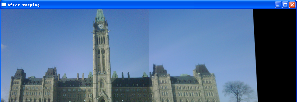
// Display the warp image
cv::namedWindow( "After warping");
cv::imshow( "After warping",result);
//需要a注意a的一點是,原-始檔案t的圖檔是按照從右至左邊進行D移動的。
// cv::Point* p1 = new cv::Point(image1.cols,1);
// cv::Point* p2 = new cv::Point(image1.cols,image2.rows-1);
// cv::line(result,*p1,*p2,cv::Scalar(255,255,255),2);
// cv::namedWindow("After warping0");
// cv::imshow("After warping0",result);
//進行Dliner的融合
result.copyTo(outImage); //圖像拷貝
int ioffset =image2.cols-100;//col的初始定位
for (int i = 0;i<100;i++)
{
outImage.col(ioffset+i) = image2.col(ioffset+i)*(1-dblend) + resultback.col(ioffset+i)*dblend;
dblend = dblend +0.01;
需要注意的是這裡不是将image1和image2進行融合,而是将原始的result和image進行融合。
由于背景比較單一,而且圖檔分辨率不是很高,是以這個結果融合的 結果非常不

目前方向:圖像拼接融合、圖像識别
聯系方式:[email protected]